Integrating a disaster recovery plan into a cabling plant

Designers and installers should plan for disaster recovery in their structured cabling systems.
Kenneth L. Masters, Key Four Inc.
Voice and data communications are increasingly becoming mission critical elements of a company`s operation. The interruption or loss of communications can severely restrict the ability of many large companies to function effectively and economically. Recognizing this, many corporations now include a loss of communications in the list of disasters for which they must plan.
Historically, disaster planning consisted of contracting for a remote hot site to serve as a backup for the mainframe computer. In today`s environment of local area networks with distributed servers, a personal computer on every desk and emphasis on direct customer support via the telephone, a remote hot site is of little help if employees cannot simultaneously call up account information on their PC and talk to a customer on the telephone. Companies are now seeking ways to provide disaster recovery sites within existing campuses and they continue to use existing support services such as security, facilities maintenance and administrative services to minimize displacement of personnel.
Design considerations
When a large consumer-products manufacturing corporation decided to replace its private branch exchange system, it requested Key Four Inc. (Tucker, GA) to design and install a voice/data backbone distribution system that would minimize the potential for disaster, and to incorporate a method of quickly establishing communications from a designated disaster recovery site within each building. The new PBX system consists of 12,000 stations located in three off-campus buildings and in seven buildings on the main campus. The main campus is served by five interconnected PBXs and two remote nodes.
The challenge in designing and installing the backbone system was to allow for alternate routing between buildings should a primary path be disrupted and also to provide for building riser-cable system recovery. This was achieved by designing a copper and fiber backbone ring to connect the five PBXs; providing a method to "patch around" a ring segment failure; and installing a riser quick connect/disconnect frame system.
Using freestanding extra-large building entrance termination frames with 110 wiring blocks, a main distribution frame was installed in each building that contained a new PBX. From these frames, multi-pair riser cables were routed to a separate designated disaster recovery site for each building. From these sites, new riser cables were installed to existing intermediate distribution frames. Disaster recovery sites were selected that minimized additional cable distance; had a high probability of continued operation after failure of the main PBX site; and had adequate heating, ventilation, air conditioning and backup electrical service.
Special attention was given to the cable routes used from the main PBX site to the disaster recovery site. Routes were used that minimized the possibility of cable damage caused by a disaster. Electrical vaults, mechanical rooms and areas easily accessible from the outside, such as underground loading docks and public parking garage areas, were avoided.
In a disaster recovery site, cables from the regular PBX main distribution frame were terminated on male preconnectorized 110 wiring blocks mounted on one side of a double-sided entrance termination frame. On the other side of the frame, new building riser cables were terminated on female preconnectorized 110 wiring blocks. The front and rear preconnectorized wiring blocks were offset vertically to allow for the front male connectors to connect with the rear female connectors. The entrance termination frame and preconnectorized 110 wiring blocks form a type of 25-pair patch panel for 3600 pairs. This arrangement allows for a portable main distribution frame and PBX to be connected into the building riser system within the disaster recovery site.
A new fiber-optic and copper ring was installed to connect four of the new PBXs. The fifth PBX was connected into the ring with a combination of new and existing fiber and copper cables. All cables forming the ring were routed through the disaster recovery sites before entering the PBX switchrooms. In addition, a wire closet was built to provide multiple connectivity options for the two remote nodes.
To minimize the possibility of damage to the backbone, no two interbuilding cables were routed in the same conduit. Where practical, separate routes were used for conduits between buildings. To reduce the need for personnel to access the disaster recovery sites and the wire closet, equipment and cables for these areas are limited to items that are necessary to support the riser and backbone systems.
The fiber ring consists of 24-strand 62.5/125 multimode Lightguide building cable terminated with ST connectors mounted in a Lightguide shelf termination cabinet. While this cabinet can accommodate 72 fibers, only 48 fibers were installed in the disaster recovery sites, and duplex-fiber patch cords were used to connect the in/out 24-fiber cables. The copper ring consists of 24-gauge 100-pair communications riser cable. Routing is basically the same as the fiber ring, with termination on preconnectorized 110 wiring blocks in the disaster-recovery sites and wire closet. The fiber ring primarily serves to connect the five PBXs, while the copper ring supports specialized circuits in one building from a PBX in a different building.
Routing between disaster recovery sites is normally made in a clockwise direction. Pass-through patching is used for circuits that do not originate or terminate in the PBX connected directly to the disaster recovery site. Should a segment of either the fiber or copper ring be damaged, a combination of clockwise and counterclockwise routing is used to establish connections among all PBXs.
Installation
Because service on the existing PBX system had to be maintained until the new system was operational, extreme care was used to install cables in existing intermediate distribution frames and telephone equipment rooms. In many locations, new conduit was installed to avoid disturbing existing cables and to improve the disaster-avoidance capability. Large riser and feeder cables were installed at night and on weekends to minimize disruption to the customer`s office functions.
Connectorized fiber pigtails were fusion-spliced to the 24-fiber cables to ensure consistent low-loss links between all fiber panels. A total path loss of less than 2 decibels was achieved even when the path contained three patch locations between end points. In existing intermediate distribution frames, new riser cables with large service loops were terminated on 110 wiring blocks mounted above existing riser feeds. The old riser cables will eventually be removed and the new riser cables lowered to align with existing station cable wiring blocks.
Disaster recovery
Should a disaster disable the PBX, the telephone equipment room or the feed cables connecting the PBX and its disaster recovery site, a spare PBX would be temporarily installed in the recovery site. The PBX, via 25-pair connectorized cables, would be connected to a portable main distribution frame built on an extra-large building entrance termination frame. Preconnectorized male/female 110 wiring blocks on the regular termination frame for the risers would be disconnected. Spare 25-pair connectorized cables would then be connected from the portable main distribution frame to the preconnectorized 110 wiring blocks where the riser cables are terminated.
Detailed crossconnect records must be maintained in a database for each PBX. To establish service from a disaster recovery site, the information from the appropriate PBX database records can be used to crossconnect the portable main distribution frame. A benchmark of 24 hours has been established to have the portable main distribution frame installed, connected to the riser system and crossconnected.
Recovery from an interbuilding backbone disaster is easier than establishing temporary PBX service. The recovery procedure is as simple as going to the disaster recovery sites on either side of the disrupted segment and repatching the required fiber and copper circuits to bypass the damage. A benchmark of four hours has been established to restore service via alternate routing.
In today`s communication-intensive business environment, reliable telephone service is essential. Designers and installers must build into their structured cabling system installation plans for disaster avoidance and recovery. Routing of critical cables must be done--after all "what-if" questions have been asked--to ensure that failure of a chilled-water or steam line will not disrupt telephone service. Furthermore, there should be plans for the rapid reconnection of a PBX to the building riser system should the telephone equipment room become unusable. Multi-building backbone cabling systems must have some type of redundancy to protect against interbuilding disruptions.
Not all disasters can be anticipated, but with proper disaster-avoidance and recovery planning, problems and expenses can be minimized. q
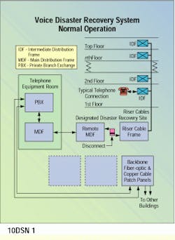
A typical riser cable routing is shown operating in normal mode in a voice disaster recovery system.
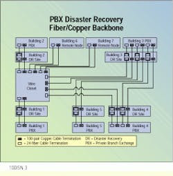
Both fiber and copper cables in the disaster recovery backbone system are routed through the disaster recovery site before entering the PBX switchrooms.
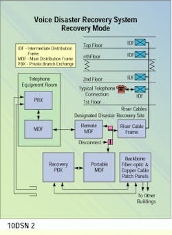
In the recovery mode, a recovery PBX and portable main distribution frame are connected to the building riser system within the disaster recovery site.
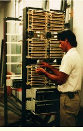
A Key Four technician terminates cable on a disaster recovery disconnect frame.
Kenneth L. Masters is president of Key Four Inc., Tucker, GA.

