Installing fiber-optic cable in premises applications
Although it is not a fragile medium, optical-fiber cable must be carefully and expertly installed to realize its full potential.
Lisa Bechtold, Berk-Tek Inc.
On the outside, fiber-optic cable may look similar to copper-wire cable, but what lies beneath the sheath is very different. As cabling installers are increasingly called upon to put in fiber backbones-and even fiber to the desk-it becomes essential that they understand this difference between copper and glass, and develop appropriate installation procedures for each medium.
There are many aspects of optical-fiber cable installation that could be examined, but two of the most important from a practical standpoint are general guidelines for installation in the building spaces most commonly associated with premises wiring-horizontal runs, runs above ceilings and below floors, runs in cable trays, riser runs-and specific procedural hints that apply to most or all optical-fiber cable pulls-jacket removal, handling core components, fiber stripping and using breakout kits.
General cabling guidelines
In whatever space your optical-fiber cable is being installed, there are some basic guidelines that must be followed. Support the cable and avoid crushing, stressing and overbending it. Every cable will have values for minimum bend radius and maximum tensile loading; do not exceed these values. Cables should never be allowed to hang freely for long distances or to press against edges in an installation.
When pulling cable in conduit, all transition points, such as those going from conduit to pull box or exiting the conduit, should be kept smooth. Sometimes the addition of a piece of conduit beyond the transition will keep the cable from resting on a sharp edge. Bushings designed to fit the ends of conduit are also available.
Flexible conduit can be placed within boxes or at interfaces to prevent pressure against the cable or scraping on rough edges. Flexible conduit can also be added in areas open to frequent access, such as raised computer-room floors, where there is a higher potential risk to the cable.
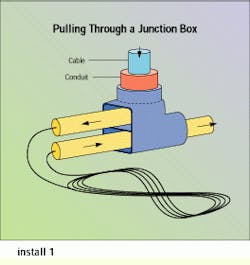
Complying with the cable`s minimum bend radius cannot be overstressed. Some applications may present conditions where the configuration of the equipment will damage the cable by overbending it if precautions are not taken. Conduit bends, pull boxes and joints must be checked to verify that the bend radius is not too small. Innerduct or flexible conduit can be used to ease or sweep the cable around tight corners. The inside radius of conduit bends for fiber-optic cable should be at least 10 times the diameter of the cable. Pulls through tightly bent elbow fixtures should be backfed; in other words, the cable is not pulled from end to end, but to and out of an opened junction box, then coiled loosely on the ground and fed through the rest of the run.
In tray and rack installations, the minimum bend radius must also be monitored, because the cable will be routed around corners or through transitions. Where raceway or rack transitions expose the cable, flexible conduit should be used for protection.
Horizontal cabling
Intrabuilding conduit runs can be in ceilings or walls or under floors, although there are certain limits because conduit systems are very inflexible. Such systems should be used only when workstation outlet locations are permanent, and where no wiring flexibility is required and outlet density is low. In-floor conduits are often embedded in concrete, making it particularly difficult to make adds, changes and moves. Conduit can be made of metallic tubing or rigid polyvinyl-chloride plastic, according to the National Electrical Code.
Conduit runs should be limited to 100 feet, with no more than two 90-degree bends between pull points or boxes. Electronic Industries Association/Telecommunications Industry Association 569, the commercial building standard for tele- communications pathways and spaces, details many of the requirements for conduit installation and sizing, and the NEC lists appropriate conduit types.
Pull boxes are installed for several reasons, including fishing the run and looping the cable for the next length of conduit. Pull boxes are not used for splicing cable. Fish tapes or pullcords should always be placed in the conduit to ease installation. Innerduct is an excellent tool for protecting cable and easing future installations.
Dropped ceilings and raised floors
Plenum runs or runs in dropped ceilings or raised floors can sometimes be the easiest to install. Many dropped ceilings or raised floors have panels that are easily removed or opened to provide fast access. Most new buildings have dropped ceilings, making this a popular method of installing cables. Raised floors are usually found in computer rooms. When the area is used for environmental air handling, the cable must be plenum-rated.
Suspended ceilings consist of low-weight panels supported by a system of metal frames or grids that are attached to the ceiling using struts or wires. Typically the panels are easily moved; when they are pushed up, they are dislodged from the grid and may be pushed to the side. If there is not much equipment in the air space, there can be ample room to work.
Cables in these spaces should be supported in some way, ideally in organized, easy-maintenance trays, wireways or racks. At the very least, cables can be supported by I-hooks or bridle rings.
Cable in trays
Cable trays or ladder racks provide a convenient, safe, efficient location in which to install optical-fiber cable. Trays can be installed in ceilings, below floors and in riser shafts. Some trays are designed to be aesthetically pleasing, so they can be placed below the ceiling and in the line of vision. Tray installation usually precedes pulling the fiber cable, because trays can be used for many other types of cable. This means that a tray distribution system may already exist. These routes may be used for installing new cable if they run to appropriate locations.
Although a tray provides sturdy support and basic protection for cable, there are still stresses to which the cable may be subjected. Optical-fiber cable should always be run in trays to avoid as much tension, crushing and bending as possible. Routes should be inspected for sharp turns, snags (sometimes from other cables) and rough surfaces. Try to run the fiber cable without pulling it under or between heavier cable or multiple cables that may stress the fiber.
The same advice holds true for moves and adds. Secure the cable to the tray to avoid damage during changes, and attach it at least every three feet.
Riser cabling
The same guidelines should be applied when cable is installed in vertical shafts or risers. If the installation requires that the cable be rated for use in risers, use a cable rated OFNR, at a minimum.
Optical-fiber cables intended for vertical applications have a calculated maximum vertical rise value assigned to them. The vertical rise is the distance the cable may be pulled vertically before being supported. It is determined by the weight of the cable and its ability to resist buckling or kinking.
To pull cable vertically, use split wire mesh grips. The device works like basket or finger grips, supporting the cable without crushing the core. Cables should be supported by cable ties, straps or clamps in wiring closets. Whenever possible, begin the installation from the top, allowing the weight of the cable to help the pull rather than adding more load.
Specific handling procedures for fiber-optic cable may vary from product to product, so abide by manufacturer`s instructions. However, some general observations can be made on the situations most often encountered in pulling and terminating this medium (for a cable pulling procedure, see "Pulling fiber-optic cable," page 44).
Jacket removal
For any fiber-count cable or cable type, some of the outer jacket must be removed to expose the fibers. For simplex or duplex cables whose jackets fit within the connector, the length of jacket removed will be specified by the connector manufacturer. Typical values for outer jacket removal for these cables are 1.5 to 2 inches. Multi-fiber cables will have longer lengths of jacket removed. Outside-plant cables that will be terminated in trays may have more than six feet of jacket removed. Mark the cable with a piece of tape to show how far the jacket should be stripped.
Interconnect cables: Simplex and duplex cable jackets are usually removed no more than a few inches from the point of termination and are easily taken off using standard buffer or jacket strippers. Round interconnect cable jackets can be removed using round cable slitters or other tools that will not damage the interior of the core.
Distribution cables: Distribution cables are provided with ripcords to ease jacket removal. High-fiber-count, unitized cables have dual ripcords. For cables with ripcords, only the first few inches of jacket need to be removed. Cable slitters or a hook knife can be used to remove the first four inches of jacket and expose the ripcords. Grasp the cable end with one hand and pull both ripcords, one at a time, with the other hand.
Heavy-duty breakout-style cables: All heavy-duty cables contain dual ripcords for jacket stripping and clear polyester tape wraps to maintain core symmetry and fiber protection. Once several inches of jacket have been taken off, the ripcords can be used.
Outside-plant cables: Outside-plant cables have ripcords and core wraps to aid in the removal of the rugged outer jacket. Be careful not to get the aramid strength members tangled with the ripcords.
Core components
After the jacket has been removed to the required distance, the clear tape and ripcords can be cut back to the jacket. In cables that have layers of aramid in the core-for example, interconnect and low-fiber-count distribution-style-trim the aramid to the necessary length as specified by the manufacturer. Aramid is most easily cut with utensils sold specifically for the purpose, although razor blades and scissors do work.
Central strength members must also be trimmed. Some are cut back to the jacket so they will not interfere with termination, and other applications call for the central strength member to be cut to a specific length and incorporated in termination (for example, in some breakout kits).
Central strength members made with fiberglass rod can be cut using almost any cutting tool. Those made with aramid inners will be easier to cut with aramid cutters. Unitized distribution cables have aramid yarn within and jackets over each subunit, which must also be cut back. To avoid connecting the wrong fiber to the wrong termination point, it may be easier to complete installation on one 6- or 12-fiber subunit at a time.
Buffer tubes on outside-plant cables are easily removed. Buffer-tube cutters are designed specifically for this purpose, but removal can also be done with a razor blade. Score one side of the tube with the razor-but not too deeply-and bend the tube away from the score. The separated piece of tube can be pulled off the end of the fiber.
Fiber stripping
Many commercially available tools will strip the buffer and coating off 900-micron tight-buffered fibers or the coating off loose-buffered fibers. Tight-buffered fibers can be stripped in a one-or two-step process. Tools sold for one-step removal will take off the buffer and coating with one action. The two-step procedure requires two tools-one to remove the buffer and another to remove the coating. Taking the coating off loose-tube fibers can be done with the same tool used for the coating of tight-buffered fibers. With some tools, the blades can be exchanged for the two functions.
The amount of buffer or coating removed will depend on the application and termination procedure. Many connectors will come with templates for this purpose. See the hardware or connector manufacturer`s specific instructions for a detailed procedure.
For the removal of cable-filling gel, try Hydrasol solvent. Any gel remover used carelessly can mar the tube printing, but Hydrasol used in moderation will not affect the identification markings.
Fiber Installation Checklist
Fiber-optic cable installations, with some foresight and care, can be done in such a way as to secure maximum cable performance. Installation guidelines include the following:
Never kink the cable.
Never exceed recommended bend radiuses, during or after installation.
Do not exceed recommended tensile loads. If you are ever concerned that you may be exceeding listed cable values or are not certain what they are, contact the manufacturer.
Do not crush the cable; avoid impacts to it.
Optical-fiber cable should not rest against sharp edges, and must be swept around corners.
Monitor tensile loading during pulls, and avoid pulling long lengths in one direction.
Plan to install extra cable protection in high-risk areas.
Do not exceed maximum vertical rise.
Secure cables in all installations. Do not let them run free over ceilings or under floors.
Plan all cable routes before beginning, ensuring the cable will not be unnecessarily exposed to hazards.
Comply with all regulatory requirements and fire codes.
A Primer on Fiber-optic Cables
Most standard fiber-optic cables fall into one of two categories: tight-buffered or loose-tube-buffered. The two cable buffer styles exhibit different optical, mechanical and cost characteristics. The loose-tube cable construction was developed for long-haul telephony applications that require a rugged, low-cost, high-fiber-count outside-plant cable solution. In a premises wiring plan, this cable type is often used between buildings. The tight-buffer cable construction was developed for both indoor and outdoor premises wiring applications. Most tight-buffer cables are rugged enough for interbuilding applications and offer the tight-buffer design advantages-ease of termination, meeting National Electrical Code flammability codes and cable flexibility.
With tight-buffered cable, a thermoplastic material is extruded directly over the acrylate coating, increasing the outside diameter of the fiber to 900 microns (0.9 millimeter), an industry standard. The tight buffer supplies the fiber with added mechanical and environmental protection, increased size for easy handling and a simple means of adding color-coding for identification. During connectorization, the buffer is stripped back to an exact length as required by the connector manufacturer.
In loose-tube cables, the coated fiber floats within a rugged, abrasion-resistant, oversized tube that is filled with optical gel. Because the tube does not have direct contact with the fiber, any expansion or contraction of cable materials will not stress the fiber.
Many optical-fiber cable designs utilize aramid yarn as the primary strength member. Some designs also use a fiberglass central strength member. Both of these materials serve as the load-bearing members of an optical fiber-cable during installation.
Core wraps and ripcords are designed to facilitate the removal of the exterior cable sheath, preventing unnecessary stress to the core. The nonhygroscopic core wrap creates a barrier between the core and the jacket, preventing adhesion and facilitating jacket removal. Ripcords provide a means of stripping back the jacket without using invasive tools that could harm the cable core.
The true cable jacket is usually the outermost element in the cable design. It serves to protect the cable against environmental hazards and gives the installer a means for managing the cable. Typical jacket materials include polyvinyl chloride, polyethylene and polyvinylidene fluoride. Unless the appropriate jacket material is used, most cables will be incapable of passing a flame test. Outer jackets are always stripped back to expose the fibers at the point of termination or connectorization.

A junction box can be used to break up a cable pull at a sharp transition. Pull the cable to the open junction box, coiling it loosely on the ground; then, feed the coiled cable through the rest of the run.
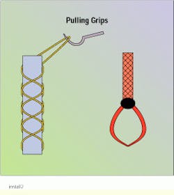
Split wire mesh grips (left) support the cable without crushing the core. External pulling grips (right) tighten around a cable as a tensile load is applied to the grip.
Lisa Bechtold is an applications engineering manager at Berk-Tek Inc., New Holland, PA.

