Telecommunications ductbanks require planned excavation
Many campus premises cabling projects need some underground ductbank.
John Jankowski, Jancom Engineering Co.
For campus environments, installers typically use underground ductbank or direct-buried cable to provide connectivity between buildings. Ductbank, an assembly of buried conduit, support hardware, reinforcing material and ground conductor, provides a pathway for electrical or telecommunications cabling. The critical nature of telecommunications mandates that physical security of the cables be a priority in a cabling installation. Outside-plant cabling must be functional and cost-effective while withstanding the effects of the environment.
The design of an underground ductbank should include surveying existing conditions, planning the route, sizing and configuration of ductwork and designing around obstacles. After these factors have been considered and resolved, the designer provides written construction documents so the installing contractor can bid and construct the project. This is especially true when the cabling system is designed by an engineer or consultant for competitive bidding, or if the excavation is to be subcontracted.
Planning the route
When researching existing conditions for planning the route of a ductbank, the designer typically uses several sources of information, including
- Visual inspection to identify obstacles and relative distances
- Record drawings (available from the facility owner, local utility or municipality) to help identify underground obstacles and building foundations
- Scaled drawings from a registered land surveyor to provide details of exposed features and changes in elevation.
If the project is an existing facility, the maintenance or facilities manager may be able to provide additional information.
Ductbank size is related to the amount of cable to be placed within the ductbank and the properties of the specific cable. The Electronic Industries Association/Telecommunications Industry Association standard--EIA/TIA-569 commercial building standard for telecommunications pathways and spaces--contains a chart of acceptable conduit fill ratios that comply with the National Electrical Code. Any size conduit can be used to create ductbank. However, 4-inch polyvinyl chloride conduit is an industry-accepted standard.
Actual duct allocation is driven by the diameter of the largest cables to be placed within any single duct. Ductbank configurations are typically dependent upon available space and the adjacent building or manhole entrance, and may often have to be altered to avoid conflicts with other utilities.
Maximum trenching depth should be maintained for protection of the ductbank. The minimum depth of cover for most ductbank designs is 24 inches. In many instances, the configuration recommends concrete encasement if future construction is planned. Also, areas of known seismic activity should be appropriately treated to minimize damage from shearing forces.
The configuration of the building entrance design is driven by the architectural elements of the building. Space requirements, protection and cable termination are documented in the EIA/TIA-569 standard and the Building Industry Consulting Service International Inc. Telecommunications Distribution Methods Manual.
Manholes are placed so ductbank lengths do not exceed the standard reel length of the required cable and maintain the maximum required pulling tension below the cable manufacturer`s specified tension. If the ductbank configuration is such that calculated pulling tensions are beyond the maximum pulling tension of the cable, the configuration must be simplified, or manholes must be added.
More information on manhole sizing can be found in the EIA/TIA-569 standard. Details for calculating the required pulling tension are available in the AT&T Outside Plant Engineering Handbook.
Regardless of how thorough the designer`s research is, obstacles can still arise when construction of the ductbank is under way; for example, existing utilities, trees or shrubs, and street or sidewalk crossings.
Trenching begins
Three or more project managers, representatives of the owner, the project designer or engineer and the contractor comprise the project management team to coordinate the effort and comply with the owner`s needs in a cost-effective and timely manner. The team should identify methods for requesting information and resolving conflicts and ensure these are followed. After the planning and documentation are completed, the trenching can begin.
Contractors should plan the trenching so minimal damage occurs. Hand-digging a trench to the maximum depth may seem tedious and costly, but any costs will be returned quickly after the first unknown (or mislocated) gas line, sewer line or primary electrical feeder is uncovered. The Occupational Safety and Health Act dictates shoring requirements for trenches that are more than 5 feet deep.
After the initial trench is dug, mechanical diggers can create uniform trenches economically and quickly--so quickly, in fact, the amount of open trench can far exceed the capability to place conduit, encasement and fill. You should, therefore, sequence the installation to maintain a minimum length of open trench. This will limit exposure to safety-related problems, as well as erosion and landscape deterioration.
Trench bottoms must slope away from the building toward the nearest manhole. There is no such thing as a waterproof ductbank, and any seepage must be kept away from the building entrance.
Installing ductbank
Assembly of the duct is simplified by the variety of quality components on the market. The most commonly used plastic conduit, PVC, is available for direct burial and concrete encasement. Installers typically assemble premanufactured fittings and spacers at the surface level, then carefully lower the conduit into the prepared trench.
Innerduct is available separately or preinstalled within PVC conduit. Because both are functionally similar, the installing contractor usually bases the choice on material availability and the installer`s skills. When installing separate innerduct, fill the conduit to capacity with three or four innerducts, depending upon the diameter of the innerduct. If only one innerduct is used, it will spiral itself within the conduit and make it difficult later to place more innerduct.
Grounding and lightning protector devices at each copper circuit termination are required by standard industry practice and the National Electrical Code. Provide additional lightning protection by placing a bare copper conductor above the ductbank, preferably cast within any concrete encasement. The conductor must be continuous and bonded to the nearest building electrical service entrance ground at each end.
The installer can lay the ground conductor on top of the conduit for encasement within the concrete, or place the conductor within the fill. In either case, the conductor must be secured at curves or transitions. The intent is to provide an electrical path, as well as a "cone of protection," to minimize the difference in electrical potential caused by a lightning strike.
Concrete encasements may be specified for an entire ductbank, and they are definitely specified for road crossings and other load-bearing surfaces. Mix the concrete for the specified strength and vibrate, if necessary, to provide proper fill between conduits, with no voids. Once the concrete is cured, move the fill back into the trench with a notification ribbon buried approximately 12 inches from the surface. Fill and tamp the trench in courses to avoid soil settling.
Cabling requirements
Any planning for a ductbank may be wasted if the planning for cable installation is not adequate. The contractor should overlay cabling requirements on the duct plan sheets to determine staging, pulling and splicing points even before the first reel of cable is on-site.
Each conduit should be filled to capacity with cable before moving onto the next conduit. However, if a conduit cannot be filled to capacity or must be left empty, the installer should place a pull rope in the conduit and label it, indicating the location of the opposite end. During cable installation in a long or complex ductbank, a running-line dynamometer can be used to measure the maximum tension used to place the cable.
Do not conserve cable when placing it through a manhole: Take the long route around from the manhole entrance to the exit. Better yet, provide a loop of cable as large as the manhole will allow. Either method provides slack cable for repair or future splicing.
Once the cable is installed, terminated and tested, the installer should label its origin and destination. Because conduits and manholes are places where water gathers, use waterproof labels and a legible permanent marking method. If problems arise with the cable later, documentation is the installer`s best defense.
Record drawings
Because of unforeseen conditions, the exact following of a project plan is rare. It is critical, therefore, to record the contractor`s findings during construction and make any other unexpected revisions to the plans. Record drawings should reflect any deviations that occur during construction.
The contractors should keep a running journal of revisions and mark them on the plan. The project engineer can then revise the drawings and issue them as record drawings. The owner then has an accurate documentation resource for future planning of any renovations or additions at the site.
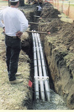
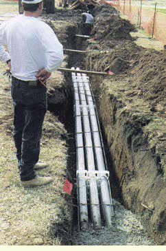
Conduit, premanufactured fittings and spacers are assembled at surface level and then lowered into a trench. Warning tape indicates buried telecommunications ductbank.
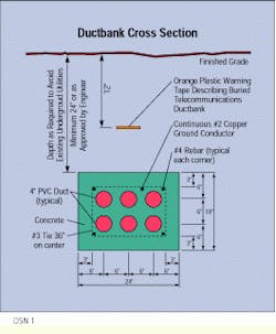
Typical ductbank cross section shows such details as size and configuration of the conduit, placement of ground conductor and depth of the trench.
Designing Around Obstacles
Existing utilities are the most common cause of conflict in routing ductbanks. The choices for placing the ductbank are simple--go under, go over or move the existing utility. Maintaining adequate depth of cover can be compromised by going over obstacles. Trenching deeper while supporting the existing obstacle increases the cost of construction. The decision is based, therefore, on security versus cost: Is the decreased security (less depth of cover) worth the cost savings?
Landscaping is important to facility owners: Trees are considered sacred. As environmental and conservation ordinances are passed in many communities, the preservation and restoration of landscaping can be critical issues in the choice of route for a buried ductbank.
The designer must also consider street and sidewalk crossings in the plan. Municipalities have requirements for permits, and campus owners usually desire uniformity and quality in any restoration record. Drawings of existing construction will provide information on whether exiting crossings are concrete or asphalt.
Plan Documentation
Plan sheets are drawn to scale and based upon surveyed information. When underground utilities are at depths to allow simple sidewalk or street crossings, the designer shows them and describes their type, size and depth. When a crossing is not a simple matter of raising or lowering the telecommunications ductbank, the installer may receive a profile sheet that describes how the transitions are to be constructed.
While the plan sheets describe the routing of the ductbank and physical features of the project site, the plan must provide installation details to describe actual construction requirements. Typical details will show:
- Cross-sectional views of the buried ductbank
- Building entrance requirements
- Views and dimensions of manholes
- Grounding and lightning protection
- Street and sidewalk crossings
- Provisions for tree protection, erosion control and landscape restoration.
Along with plan sheets, narrative specifications provide such information as the project description and scope of work of the installing contractor, acceptable products to be used and the execution of the project.
The scope of work describes the project, its goals and limitations, schedule, and applicable codes and standards. It identifies the parties and the obligations of each party regarding completion of the project.
The selection of products to be used in construction is left to the installing contractor. However, the specification provides a clear standard of quality for, if not a listing of, specific products.
The execution section of the specifications controls how the project is to be performed. Standards of quality for workmanship, appearance, staging and storage of materials and clean-up are detailed.
John Jankowski is vice president, telecommunications, at Jancom Engineering Co. (Austin, TX).


