Installing backbone cabling systems
Design, installation and user considerations are vital to putting in building backbones.
Scott Partington, Berk-Tek Inc.
The backbone system consists of connections between entrance facilities, equipment rooms and telecommunications closets. Backbone systems are often referred to as riser systems because in many installations the bulk of the system, especially the cable, is installed in a vertical riser. In multistory buildings, for example, the backbone connects the equipment or computer room in the basement with telecommunications closets located on every floor.
In a campus environment, however, the backbone may run horizontally, connecting different entrance facilities or remote telecommunications closets. In some applications, then, there is no real difference between the terms "horizontal" and "vertical." Physical topologies may vary, and sometimes connections don`t fit our assumptions about what a backbone is.
The main requirement of a backbone system is that it be able to support many different user applications, from simple voice transmission to very unforgiving high-speed data and multimedia networks. To meet this requirement, system designers and installers must use foresight when planning a backbone system. Installations today have to anticipate future growth and prospective applications as well as current needs. For this reason, many backbone installations depend on optical fiber, and can include dozens of spare fibers, if not actual cables. Another recent trend is to install hybrid fiber-optic cables in the backbone, terminating and using the multimode fibers but leaving the singlemode fibers dark, or unused, to support future needs.
Backbone cabling systems that are being installed can usually be classified into one of four different topologies, each of which has its own characteristics. To properly install these systems--Ethernet, token ring, fiber distributed data interface, and asynchronous transfer mode--it is essential to know, at least in a general way, how they function.
Ethernet, FOIRL and 10Base-FL
The fiber-optic inter-repeater link, or FOIRL, section of the 802.3 standard of the Institute of Electrical and Electronics Engineers expands the scope of the traditional Ethernet topology. As specified in IEEE`s 802.3 10Base-5 specification, large 50-ohm Thick Ethernet, or Thicknet, trunk cables are accessed using vampire taps that pierce the cable to contact the conductor at specific intervals of 2.5 meters. (This explains the bandmarks on the cable jacket.)
Transceivers connect to the taps. Attachment unit interface or transceiver cables attach the transceiver to the data terminal equipment, usually a workstation or hub that services several nodes. Ethernet trunks are often used in large networks, with each coaxial-cable segment running up to 500 meters without repeaters in a physical bus topology.
More flexible 50-ohm Thin Ethernet cables, also called Thinnet, are often installed to support smaller networks, limited to 185 meters. The relevant specification is IEEE 802.3`s 10Base-2 document.
Less-expensive Thinnet is a good option for Ethernet networks that are limited to a small geographical area and relatively few users, such as a single office or department. Workstations are linked in a bus topology, but the cable can be directly attached to the workstation, creating a daisy-chain. Both 10Base-5 and 10Base-2 are designed to run at 10 megabits per second.
When considering a 10Base-5 or 10Base-2 network, it should be noted that neither is recommended by the TIA/EIA-568-A commercial building wiring standard of the Telecommunications Industry Association and Electronic Industries Association (both in Arlington, VA). Both networks use a bus topology, which is significantly different from the star topology recommended by 568-A.
For 10-Mbit/sec Ethernet, you can use a 10Base-T system running on unshielded twisted-pair, or UTP, cable.
Another wiring scheme that supports optical-fiber links within the traditional scope of an Ethernet network is 10Base-FL. A fiber-optic transceiver is attached to the network via an attachment unit interface. Applications of 10Base-FL include connections where the cable is exposed to extremely high interference, such as in a factory environment. The 62.5-micron fiber cable used for the backbone is immune to electrical interference.
Whether installing a new Ethernet network or expanding an old one, FOIRL should be considered. The FOIRL specification details requirements for a point-to-point optical-fiber link designed to increase the overall length of a 10Base-5 network. The inter-repeater link is the medium that carries the signal between a set of repeaters. It is not intended for connection to data terminal equipment. If optical fiber is used, the distance between repeaters can be extended up to 1 kilometer. Repeaters are not counted as nodes in the network structure; they merely receive and repeat information and are transparent to users. An FOIRL backbone can be used to connect two distinct network segments, such as two independent but compatible segments in different buildings.
Only two fibers are required for an FOIRL--one to transmit and one to receive; however, more are often installed to guarantee future upgradability. The IEEE standard accepts a variety of fiber sizes, although 62.5-micron fiber is most common. FOIRL is intended to run at the 850-nanometer window, using a bandwidth of 150 megahertz-kilometer. Cable attenuation should be below 4 decibels per kilometer. As part of an Ethernet system, the FOIRL runs at 10 Mbits/sec, well below the fiber`s actual capacity.
Token ring
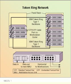
Token ring is based on the IEEE 802.5 standard, "Information Technology--Local and Metropolitan Area Networks. Part 5: Token Ring Access Method and Physical Layer Specifications." It is designed to run at either 4 or 16 Mbits/sec, and is set up in a token-passing ring configuration. The network topology is considered to be a logical ring because it is often configured physically in a star design, especially when UTP cable is used in the horizontal cabling system. This topology also utilizes TIA/EIA-568-A`s structured wiring approach.
A multistation access unit, or MAU--basically a concentrator--is used to create the physical star. The unit--an IBM 8228 or 8230 CAU--is a vendor-supplied hub that connects to the network backbone, originally comprising 150-ohm shielded twisted-pair, or STP, cable. The extended capacity and distance that optical fiber provides has increasingly made it the backbone medium of choice for token ring networks.
Each MAU in the network provides not only attachment to individual workstations using a variety of media, such as UTP, STP and even coaxial cable, but also supplies connections to other MAUs. The logical ring topology means that stations are technically attached sequentially, although the MAU can bypass any station.
Every MAU is attached to both upstream and downstream units via ring-in and ring-out ports. When Type 1 cable is used, each port is connected with two twisted pairs. One pair is the primary data path, and the other is the backup path. All MAUs in a token ring network should be connected using redundant paths in the main ring. When one link is disrupted or becomes disconnected, the bypass mode becomes operational, using both pairs of one cable. Horizontal connections to workstations are not redundant, since they are expected to power down. The MAU will automatically bypass any node removed from the network.
Optical fiber can also be used for the backbone. It may be required where backbone distances exceed the standard capability of STP cable, such as in a campus environment. Maximum network distance will vary depending upon the number of nodes attached, the bit rate to be carried and whether the hardware is passive or active.
Fiber distributed data interface
Developed by the American National Standards Institute (New York, NY), fiber distributed data interface, or FDDI, has become one of the most widely specified standards in the industry. Designed for multistation networks working at up to 100 Mbits/sec, this standard is an attempt to regulate present trends as well as anticipate the needs of future networks. FDDI was originally written using optical fiber for all parts of the network.
ANSI`s FDDI physical layer medium dependent standard details requirements for all attachment devices linking to the fiber-optic network interface. Also included is information on power levels and optical characteristics of the transmitter and receiver, interface signal requirements, acceptable bit-error rates and optical fiber cabling plant needs. (The term "cabling plant" is used here to refer to all fiber-optic components between stations, including cables and connectors.)
FDDI systems are closed-loop networks using a token-ring architecture. A string of stations is connected by a dual-ring topology, where signals are transmitted in two directions concurrently to prevent signal loss in the event of cable or component failure.
In a conventional copper-wire token-ring system, a token bearing a message is passed along the network until it is received by the station or node to which it is addressed. This token is retransmitted by each node in the network until the message reaches its destination, the token is returned to its origin, and the message is canceled. Only one node at a time may transmit. If the message-bearing token is received by a node that is about to transmit, the node must pass the token along the network and wait until it is received again and the previous message has been canceled.
FDDI modifies this simple token-passing system by allowing more than one token to be circulated at any time, with each node releasing the token as it is transmitted, not when it is returned. This, along with the use of fiber-optic transmission media and other high-level networking components, allows a 100-Mbit/sec speed. Applications for FDDI include computer-aided design and manufacturing stations, as well as back-end, real-time, metropolitan-area and campus connections, although the scheme is most often used in the backbone.
An FDDI backbone system is used to connect separate networks or components, which may be in different buildings or different areas of the same building. Separate networks using Ethernet, token ring or other systems are connected to the fiber-optic backbone using commercially available gateways that allow the different networks to communicate. Using the FDDI backbone, the various network users may also be attached to a host computer, front-end processor or other computer-room equipment. Data transfer and communication are efficiently carried out at high speeds.
FDDI network components
FDDI does not specify a cable type, but lists cable-plant optical characteristics. The cable plant includes all cable, connectors, switches and splices. The use of the term "cable plant" is important here, because FDDI calls out attenuation as a function of the entire link and not just the cable.
Multimode 62.5/125-micron fibers are the medium specified by the ANSI standard. Parameters for other fiber sizes are listed, but maximum system distance may be diminished if they are used. Theoretical connection losses caused by mixed fiber sizes are also given in the FDDI documentation.
Optical bypass switches allow any component in an FDDI network to be isolated from it without breaking the ring. When optical bypass switches are included in the network, part of the cabling-plant loss budget must be assigned to these switches. The loss and bandwidth specifications provided include a worst-case bypassed configuration.
The media interface connector is the physical connection between the cabling plant and the node or station. FDDI lists requirements for the plug (male) and receptacle (female) part of the connection. This ensures that cable connectors will properly mate with the connection interface. Any plug construction is allowed that matches the geometry of the receptacle, which is described in detail. These requirements are numerous, so the FDDI specification should be consulted before proceeding. No connection loss is listed, but it must be determined and included in the optical power loss budget. FDDI plugs and receptacles are commercially available.
Concentrators are attached to the network to allow multiple station access for stations not directly attached to the dual ring. Nodes that are always active will be attached to both rings of the network and are referred to as dual-attachment stations. Dual-attachment stations are connected to the second ring as a backup in the event of cable or node failure. If the system recognizes a fault on the primary ring, it uses the secondary ring for transmission, keeping the rest of the network operational. Due to the high system reliability created by this backup, dual-attachment station connections are used for demanding applications, such as trunk links.
Single-attachment stations are used for workstations or nodes not attached to the secondary ring. Network integrity is maintained using the dual-attached concentrator, while the single- attachment station connections are made to the concentrator in a starlike pattern. These connections are used for workstations that are often powered down.
Asynchronous transfer mode
In the last few years, asynchronous transfer mode, or ATM, has come to be viewed by many as the end-all and be-all in high-speed backbone solutions. While many have considered ATM to be a panacea for the problems of network interfacing over the public network--for long-distance, wide-area communications--the scheme is increasingly finding applications not only in the premises backbone, but all the way to the desk. As a bandwidth-efficient, transparent technology, ATM offers many real benefits.
ATM is largely the result of work on broadband integrated services digital network, or BISDN, standards. The intention of ISDN is to provide an international standard for end-to-end digital, high-bandwidth transmission of voice, data and signaling. ATM is a specific type of service defined as part of the general BISDN concept. Packet technologies, of which ATM is one, transport information using cells that contain the address to which they are sent. ATM uses relatively small, fixed-length packets, referred to as cells.
The actual ATM cell is 53 bytes long. A 5-byte header, bearing the address, is accompanied by a 48-byte information field. For a cell-relay system such as ATM to work, all cells must be of the same length. Frame relay, a more familiar technology, uses frames that vary in length. The specific, unvarying size of the cell is one of the things that makes cell relay highly efficient.
Many current methods of information transfer use a time-division multiplexing or synchronous transfer mode technology, which is significantly less efficient than cell relay. In time-division multiplexing, each of the users along a communications channel is given a particular segment of time for transmission, regardless of how busy the user is. A user who is "down" or offline is provided with as much time on the link as a user attempting to transmit an extremely large piece of information, and there is no simple way to reallocate the time. Time-division multiplexing is often referred to as synchronous transfer mode because of the synchronous or synchronized flow of data; the user allocated the third time slot will always show up in the same place. If there are three users, the user with the third time slot will have slots 3, 6, 9 and 12, for instance, with every frame, whether or not there is information to be transmitted.
Cell relay is more equitable in its segmentation of available bandwidth. Users may grab the entire bandwidth if they require it and it is not being used. If users have nothing to transmit, they receive no bandwidth. Since the information is divided into fixed-length cells, a sporadic user will be able to access the channel between the cells of even the heaviest user. Large pieces of data are separated into smaller pieces to allow this kind of access. The pattern or chain of users on the channel will vary depending on which users are active and the amount of information each must transmit. In this scheme, the traffic is said to be aligned asynchronously. Users are identified by the 5-byte cell header rather than their position in the sequence.
The fixed-length cells of an ATM system offer more than bandwidth efficiency. ATM also lets the channel be used by many different functions concurrently. Since the information is divided into specific cells, virtually any application can make use of ATM. It can carry voice, video and data from Ethernet and token ring networks at the same time, without concern about local or wide area network compatibility.
Furthermore, ATM is capable of handling bursty traffic. The user takes bandwidth as required, without having to pay for an expensive, dedicated line that may sit idle most of the time. ATM is very attractive for use in the public network, where the cost of usurping large amounts of bandwidth creates a host of irritated computer operators.
While it is important to carefully design and install the horizontal portion of any network, it can be even more vital to provide an adequate backbone. For this reason, planning well into the future of a network is recommended for its backbone installation. System designers are increasingly using optical fiber in the backbone to provide a large bandwidth potential for projected applications that will require expanded capacity. Many of the fiber backbones installed years ago will continue to support prospective networks many years from now.
On the other hand, improvements in manufacturing within the last few years have brought UTP cables back into the network in a substantial way. UTP cabling has become the medium of choice in the horizontal portion of high-speed networks. New standards for cable performance, as well as improved manufacturing and engineering practices, have produced high-pair-count UTP cables that are suitable for backbone applications.
Defining the Backbone System
Some definitions may help your understanding of the different parts that make up a backbone cabling scheme:
-Backbone cabling system: the part of a premises distribution system that provides the physical connection between entrance facilities, telecommunications closets and equipment rooms.
-Crossconnect: a device for terminating the permanent wiring of a premises; it allows for interconnection or crossconnection. Also called a distribution frame.
-Equipment room: a space that houses the telecommunications equipment that serves a premises. It is distinct from a telecommunications closet in that the equipment itself is more complex. The equipment room may house devices for private branch exchange service, mainframe or host computers and front-end processors, and connection to the premises backbone system.
-Horizontal cabling system: the cabling and components between the telecommunications closet and the work area. Individual cable runs are called links, or channels. Not part of the backbone cable system, but connected to it.
-Keying: a feature of a connector system that prevents physical mating where the service or orientation is incorrect. For example, keyed jacks may be used on all data connections to prevent plugging them into the phone system. Some networks, such as fiber distributed data interface, have distinct keying guidelines and requirements.
-Link: a cable run between two devices in the horizontal cabling system. For the distinction between link and channel, see Technical Systems Bulletin 67 of the Telecommunications Industry Association (Arlington, VA).
-Telecommunications closet: an enclosed space, usually a closet or cabinet, used for housing telecommunications equipment, crossconnect wiring and other devices. This is the transition point between the horizontal and backbone cabling systems.
-Telecommunications entrance facility: the location where telecommunications services are brought into, and terminate within, a premises.
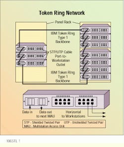
Twisted-pair copper cable is used to wire this token ring network in a physical star. Each multistation access unit is connected to the units upstream and downstream via ring-in and ring-out ports.
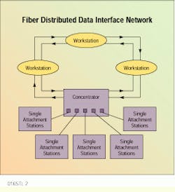
In a fiber distributed data interface network, single-attachment stations are hooked up to a concentrator, which in turn is a part of the system`s ring topology.
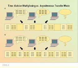
With time-division multiplexing, each user is allotted bandwidth, even if nothing is being transmitted (a). With asynchronous transfer mode, users take the bandwidth that they need, and no more (b).
Scott Partington is fiber-optic product manager for the Electro-Optics Division of Berk-Tek Inc., Fuquay-Varina, NC.

