Kim L. Ferguson and Anthony P. Nuciforo, Robert Derector Telecommunications
To ensure that installers in the field are working with the latest documents, always start with an accurate and well-coordinated drawing package.
Maintaining accurate design and installation drawings is critical to the success of any construction project. Failure to keep these documents up-to-date can lead to unnecessary reworking of already-installed components, costly change orders and, perhaps worst of all, delays in project completion. The best way to keep your drawings current, of course, is to minimize the need to change them in the first place. However, even the most carefully planned designs are likely to change during the course of construction. How can you ensure that installers are always working with the latest drawings? The best solution is a combination of up-front planning, skillful project management and efficient communications of updated information to the field.
For small, in-house cabling projects, keeping design, installation and as-built drawings current is a straightforward task, particularly if you are using a computer-aided design (CAD) system. On the other hand, large new construction and major renovation projects present more-complex and difficult challenges. First, major projects require a large, diverse team of architects, engineers, consultants and outside contractors, each concentrating only on his or her aspect of the job. Second, larger projects generate changes at a faster rate and at a much higher volume than a smaller job.
Finally, because design changes on a large construction project often have major financial and scheduling implications, proposed changes are often evaluated for extended periods before they are approved for implementation. Days or weeks may pass from the time a change is proposed until the revised drawings are released to the contractor. Meanwhile, the installation work continues, with design elements sometimes being built according to outdated specifications.
Always begin with a set of accurate, detailed and fully coordinated design drawings. Apart from helping to get comparable bids for the work involved, a good drawing package can minimize changes that result from unforeseen field conditions. It also forms the basis for an accurate set of as-built drawings.
When planning your drawings, keep in mind that each member of the project team will use your drawings for a different purpose. For example, the architect is concerned with location and size of equipment spaces as they relate to other building elements, as well as the location of telecommunications outlets in each office or workstation. The engineer, on the other hand, wants to know how the locations of telecommunications pathways--that is, cable trays, conduits and other raceways--will affect other building systems above a hung ceiling or under a raised floor. The contractor has to consider all these factors and others, such as where particular devices are mounted in equipment rooms and racks. A good drawing package will incorporate all the specifications required by each member of the team.
The purpose of these site drawings is twofold: First, these documents, together with a set of detailed written specifications, form the basis for the bid package that all potential contractors will use to estimate their fees for the work. As such, they must explicitly represent the full scope of the project, so that valid bids can be obtained and change orders minimized. Second, the drawings will be used as the blueprints for the actual installation work, so they have to provide enough of the right kind of information for the installation crews.
Communicating information relative to the installation process is far more important than making pretty drawings. Showing a particular piece of equipment, such as the faceplate of a local area network (LAN) hub or a patch panel, in life-like detail may not be essential from an installation perspective. Instead, make sure all the equipment planned for a rack or cabinet actually fits. For example, take time to verify that the 24-inch-wide by 6-inch-deep cable tray shown in the drawings fits where specified. Conduct detailed coordination meetings with the design trades contractors who will affect, or be affected by, the telecommunications work. If working on a retrofit or renovation project, go into the field and conduct detailed surveys of the areas that will be affected by the work. This will help minimize drawing changes from unforeseen field conditions.
Minimize changes
While well-coordinated design drawings help to minimize drawing changes, they will not eliminate them. Unforeseen field conditions, such as architectural or technological changes, will inevitably occur. To ensure that their impact on telecom- munications is well understood and the appropriate changes are quickly communicated to field installers, you should know when changes are coming and what`s happening in the field. And, always have a good change-management process in place.
Know when changes are coming: Stay proactively involved in the overall project management and design process by attending project meetings regularly--even those that may not relate directly to telecommunications. On many occasions, architectural changes are discussed or initiated at space planning and coordination meetings between architects and engineers or between different engineering disciplines. Battles for the often-limited above-ceiling and under-floor spaces are frequently fought here.
Any meetings during the construction phase of a project almost always result in design changes. Attendance at these sessions will keep you abreast of changes that will affect your work. You may actually get others to modify their work instead of yours. (If you are not there, you can bet your work will get the bulk of the changes.) In addition, try to include representatives of your contracting and installation company in these meetings. Not only are they in a position to know what changes are coming, but their expertise can often be helpful with difficult design or coordination issues.
Know what`s going on in the field: At all times, keep track of the project as it progresses. This will help you prepare for the proposed impact that changes might have on your work. Establish a regular schedule of field observation visits during the installation period and, when possible, include a member of the contracting or installation team in the walk-throughs to discuss the work being reviewed. Well-executed field observations have the added benefit of allowing you to identify potential conflicts before they become problems.
Have a good change-management process in place: Early in the project, establish a procedure for managing the change process. Based on the size, scope and complexity of the work involved, this process will vary from project to project; however, once established, it should be followed religiously. Change-management procedures are usually established by the architect, general contractor or construction manager. In this case, the easiest approach is to follow or parallel the change-management program already in place. These professionals have done this many times before and know what works.
Change-management process
If no change-management process exists, you will have to develop one. Several approaches can be considered; for example, you can establish a single point of contact to collect and organize all requested changes. This does not necessarily have to be one person, but could be a committee of two or more people who will meet regularly to process requests. Because change requests can arise for different reasons--architectural design changes, field modifications or the introduction of previously unanticipated technologies--each request may require slightly different collection and evaluation procedures.
Another approach is to process change requests on the basis of the impact they have on the project, not necessarily on a first-in, first-out basis. For example, a request to relocate a cable-tray run to avoid conflict with ductwork being installed should have priority over a request to relocate outlets in an area not yet under construction.
After changes are approved, identify a single source (individual or committee) to issue direction to contractors and installation crews concerning such changes. Nothing is more confusing than revised drawings and design changes flowing to a contractor from several different sources simultaneously. This can cause delays as questions are raised about which changes are more recent and what work takes precedence. The resulting chaos can be avoided by establishing one "official" channel for this information.
Finally, establish standardized methodologies for communicating in an unambiguous way to contractors and installers. How this is done depends on the size and type of project.
Communicating information to the field
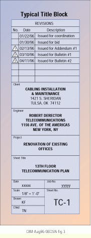
The best way to communicate information to the field is to revise the original design drawings to reflect the required changes and then issue them to the installers. Architects and engineers traditionally revise drawings by "bubbling" (highlighting) the changes to let the contractor quickly identify what changes have been made. A small triangle with a sequential revision number in it is usually attached to the bubble. This number is keyed to a revision date that appears in the title block of the drawing, so that everyone knows when the revised drawing was issued. Each time a drawing is revised, the previous bubble is removed to avoid confusion. However, the revision triangle and dates are always left in place as a record of the drawing`s history of modification.
Note: If you issue more than one drawing as part of a revision package, it is advisable to send a list of changes describing the modifications made to each drawing.
Sometimes changes are too small to warrant revising and reissuing an entire drawing or set of drawings; for example, the addition of a single telecommunications outlet to one or more floors of a building. In this case, it may be more appropriate to issue a simple sketch showing only the area or areas affected by the change. Another instance where a sketch may be useful is to show a coordination detail, such as the placement of a pathway system in relationship to some other building element.
If the changes are simple enough, a drawing may not be necessary. A brief letter or memo will suffice. However, this method should be reserved for changes that can be clearly explained in one or two paragraphs.
Field changes can be made by hand- annotating a contractor`s drawings at the construction site. This method is particularly useful for making minor changes to pathways or cable routing, hardware placement in an equipment room or outlet locations. However, use this method only for changes that do not impact cost, scheduling or the work of other trades.
A "living" record
When you communicate changes to the field using markups, sketches, letters, memos or even verbal instructions (not recommended), remember that you must also update your original drawings with this information. This is essential to reflect as-built conditions so that the next set of drawings will not conflict with information previously issued.
To ensure that updates are always made to the latest set of drawings, establish a master, or record, set of drawings that is updated regularly. The baseline for these drawings is typically the original bid set prepared and issued at the start of the project. As these drawings are updated, they become a "living" record of all the changes and modifications made over the course of the project and will also be invaluable for the ongoing management of the installation.
The process and procedures outlined in this article are just as valid for ongoing moves, adds and change projects as they are for new construction and major renovation projects. Accurate, up-to-date drawings will be a critical component of any efficient and cost-effective cable-management system. Change is a normal and integral part of any project, so always ensure that you have a good change-management process in place. Even after a project is finished, precise as-built drawings make ongoing system maintenance simpler and more efficient. q
Kim L. Ferguson and Anthony P. Nuciforo are principals of Robert Derector Telecommunications, New York, NY. The company specializes in telecommunications engineering.
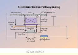
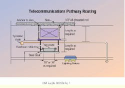
Drawing of telecommunications pathway routing helps to identify the coordination required between tradespeople to install pathways for cabling and wiring.
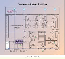
Newly changed areas are "bubbled" in this floor plan, identifying outlet types and IDs with cross-references to equipment-room layouts. Revision triangles identify areas changed in previous issues of this drawing. Notes clarifying or expanding on information in the drawing are usually found in the lower right-hand corner.
Title block on a drawing tracks the history of this "living" document and provides related project information. Revision triangles are not added until the drawing has been issued for bid.
Components of a Good Drawing Package
While the details of what should be included in a drawing set will vary according to project requirements, some basic information should be included in all packages. Unless otherwise noted, all drawings should be to scale to allow for accurate cable-length takeoffs and to show that things actually fit where intended. Drawings should also illustrate all existing conditions, such as beams, piping and duct work, that would impede or otherwise adversely affect an installer`s work.
Floor plans, at a scale of 1/8 inch = 1 foot, show the locations of all equipment spaces, pathways, cable routes and outlet locations. If there are multiple telecommunications closets on the floor, the drawings indicate which closet serves which outlets. All outlets are labeled with a unique alphanumeric identifier for cable-pulling and cable-termination schedules. Equipment spaces are tagged with a pointer indicating the drawing where details of that space are shown. If floor plans show conduit runs, the drawing indicates the quantity and size of all conduits, as well as the size and locations of pull and splice boxes.
Part plans should be scaled at 0.5 inch = 1 foot for such equipment spaces as equipment rooms, service-entrance facilities and telecommunications closets. Part plans show the exact location in the space of telecommunications and related equipment (such as power distribution and HVAC equipment). If the room has an overhead cable-tray system, show two part plans for each room. One normal floor plan shows the equipment as described above. If the room has a raised-floor grid, show this on the plan to facilitate the placement of equipment with respect to tiles and tile cuts. The other part plan is a reflected ceiling plan that shows the location of the overhead pathways with respect to lights, diffusers, ductwork, sprinklers and piping.
For each part plan, use a set of sections and elevations, also at a scale 0.5 inch = 1 foot, showing the placement of all equipment and termination hardware on walls and in cabinets. Do not waste time drawing detailed patch panels, punchdown blocks or LAN hubs. Scaled rectangles with alphanumeric designators are sufficient to identify each component type or function. This saves valuable drawing time, and your CAD system will regenerate drawings faster if it does not have to draw every port and switch on every LAN hub or patch panel.
Use detail sheets, scaled to show necessary or appropriate installation details, such as mounting and supports for cable trays, rack and cabinets, firestop and through-wall penetrations, equipment grounding, and cable and equipment label placement.
Single-line diagrams show the types and quantities of all inter-rack and intercabinet cabling.
Riser diagrams show all backbone pathways and cabling requirements.
In addition, a set of detailed pathways, cabling and grounding specifications, and a full set of cable-pulling and cable-termination schedules should accompany these drawings.


