Tracking interference from power-system harmonics

Power surges and failures aren`t the only threats to your telecommunications network. Harmonics can also cause problems. Here`s how to track them down.
Dick Troberg, Fluke Corp.
You have just completed the installation of a cabling system for a new high-technology office building. During the building and testing phases, the job went smoothly. But now, after only one week of operation, the building manager complains of interference on several of the incoming cable pairs. Then the finger-pointing starts, and you agree to take a look. What can be causing the problem? It obviously wasn`t there when you completed the acceptance testing.
Modern commercial and industrial buildings typically contain a number of different electrical systems. These systems can include power distribution, telephone, energy-management controls, audio, time-clock synchronization and computer networks. Ideally, these systems operate independently of one another, with no unplanned interaction, but the laws of electromagnetism, combined with Murphy`s law, may dictate otherwise.
Fiber optics are essentially immune from electromagnetic interference, but cabling systems built with copper conductors are prone to interference from two primary sources: stray magnetic fields and ground loops. Both of these sources are related to the power-distribution system and its associated equipment. For cabling installation professionals, a good understanding of power-distribution systems will save considerable time when troubleshooting interference problems on copper conductors.
The power-distribution system as we know it today has evolved over the last 100 years, guided by the National Electrical Code (NEC). The NEC deals primarily with fire-prevention and electrical-shock safety; it relates only indirectly to user convenience and system efficiency.
Power system harmonics
Over the last few years, operation of the power system has undergone a dramatic change, driven by two factors: the increasing need for energy conservation and the emergence of low-cost power semiconductors. The combination of these forces has resulted in a large number of nonlinear loads being connected to the power system. These loads generate distorted currents, which contain higher-than-normal frequencies called harmonics. These harmonic currents, in turn, generate stray magnetic fields and ground loops--what we don`t want near our cabling system.
If you are going to successfully troubleshoot interference from power-system harmonics, you`ll need to understand some basics, including how harmonics are generated and how they flow around the power system. Next, you`ll need a systematic approach to finding the source of interference. And finally, some ideas for potential solutions will be helpful.
Harmonic currents are formed by action inside a nonlinear load. A typical nonlinear load will have power semiconductors that switch the current on or off suddenly within each cycle of the line voltage. The usual purpose of the switching action is the conversion of line alternating-current (AC) power to variable amounts of direct-current (DC) power required by the load. Examples include the DC power supply of a personal computer or the input to an adjustable-speed motor drive. Other examples include an incandescent lighting dimmer or a solid-state heater control. In these cases, the switching is used to regulate the amount of AC power reaching the load.
In either of these cases, the switching generates higher frequencies within the AC line current. What you want to know next is, Which frequencies? The rules of mathematics and physics dictate that harmonics of the power-line frequency will be whole-number multiples of the base frequency--60 hertz in the United States and Canada. The rules also state that the harmonics of power-line current will be only odd multiples of 60 Hz, assuming the load is functioning normally.
Although the table on page 88 lists power-system harmonics up to the 13th, in actual practice, harmonics up to the 50th (3 kilohertz) may be present in a power system. It is unlikely, however, that frequencies above 3 kHz will be present in power-system current.
Troubleshooting
The table also provides information that will help in troubleshooting. First, it indicates which frequencies are likely to be present if the source of interference is power harmonics. Second, it gives the sequence that corresponds to each harmonic frequency. Sequences come in three categories: positive, negative and zero. In a three-phase power system, the sequence determines which conductor will carry which set of harmonics.
For troubleshooting, it is always helpful to know which nonlinear electrical loads produce which set of harmonics. To break this down, you can separate common loads into two groups according to how they are connected to the power line. The first group is connected single-phase, and includes receptacle and lighting loads. The second group consists of three-phase loads such as those of large mainframe computers or adjustable-speed motor drives.
Note that the nonlinear single-phase loads generate mostly 3rd harmonics and the nonlinear three-phase loads generate predominantly 5th and 7th harmonics.
Analysis of a simplified schematic of a typical commercial building, shown on page 86, helps to identify the expected path of individual harmonics. The rules for harmonic flow are as follows:
- Phase conductors carry all harmonics generated by the load.
- In a balanced three-phase, 4-wire system, the positive- and negative-sequence harmonics will cancel in the neutral conductor. The zero-sequence harmonics, however, will add algebraically in the neutral.
- Zero-sequence harmonics will be trapped in the first delta-connected transformer winding, typically in the primary of the transformer feeding receptacle loads.
With this information, you can outline a troubleshooting process for locating interference from power-system harmonics.
- First, use a portable oscilloscope to measure the frequency of the interference.
- Next, make a walking tour of the facility to determine the location of possible sources of interference, and the location of cable runs that may be near the source itself or near the conductors and transformers feeding the source.
- If the interference frequency corresponds to a zero-sequence harmonic, look carefully at cable runs near neutral conductors; for example, overhead telephone pairs on power poles.
- If you determine the interference is possibly caused by a ground loop, look carefully for illegal neutral-to-ground bonds in subpanels.
Remember that the National Electrical Code requires that the neutral and ground conductors be bonded together only at the service entrance or at the secondary of an isolation transformer. (This is technically called a separately derived system.) q
Dick Troberg is senior product specialist at the Service Tools Division of Fluke Corp. in Everett, WA.
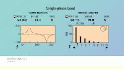
The typical current waveform and harmonic spectrum for a single-phase load is shown on this Fluke 41 Power Harmonic Analyzer output. The output is akin to fingerprints and can be used to identify potential sources of harmonic interference. For instance, nonlinear single-phase loads generate mostly 3rd harmonics.
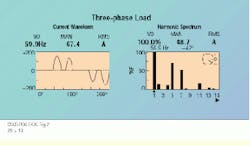
The typical current waveform and spectrum for a 3-phase load, shown as the output of the Fluke 41 Power Harmonic Analyzer, consists mostly of 5th and 7th harmonics.
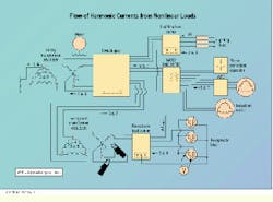
This simplified schematic of a power-distribution system shows the flow of harmonic currents from nonlinear loads. Note the two ground symbols in the schematic. If the neutral and ground are bonded together at any other location, some of the neutral current will flow in the ground conductor, causing an unwanted ground loop.

