Troubleshooting residential and light-commercial wiring
Testing cable runs and troubleshooting faults can be simple if you use the proper tools and procedures.
Michael Shatzkin / Leviton Telcom
Testing cable runs in residential and light-commercial low-voltage installations is relatively simple--and it can be much simpler if done during rough-in, before installing drywall. In addition, if you test your cable runs before installing jacks or other devices, it will be less difficult to isolate faults. Selecting the proper tools to perform this work is as important as choosing the correct time to test and troubleshoot cable runs. Using testing and troubleshooting equipment specifically designed for telephone installation and repair will speed and simplify troubleshooting.
It`s true that many of these tests and troubleshooting procedures can be done with less-sophisticated equipment not designed for this type of work. For example, troubleshooting and wiring verification involves detecting continuity, measuring voltage, and determining polarity. While these tests can be done using a volt- ohmmeter, it is easy to misinterpret a meter reading or to forget one test during a sequence repeated many times during a complex series of tests that involves many different conductors. Experience has shown that when substitute test equipment is used, testing procedures take longer, may be less reliable in finding the fault, and frequently will identify only part of the problem.
Using the proper equipment, on the other hand, often simplifies the task. For instance, test equipment using visual indicators such as colored lights, or audible signals such as beeps and tones, will ease the installer`s job and result in fewer errors and callbacks. Also, streamlining both the test procedures and the equipment needed enables any installer--regardless of expertise or skill level--to achieve more-dependable results.
Toner and probe
The tone test set and inductive probe are among the basic instruments used in a telephone installation. They are used together to identify where particular wires are located, broken, or terminated in a horizontal cable run. A tone test set generates a tone that is transmitted down a wire; the inductive probe is used to detect the tone and identify the wire carrying it. The probe is said to be inductive because it can detect tones without actually connecting to the wires under test. This capability is useful for tracing wire and cable circuits, as well as for locating faults, even through drywall or within large cable bundles.
Tone test sets and inductive probes offered by different manufacturers are available in a number of different models, which vary in price depending on the features. One of the features you may want to consider is the ability to transmit one continuous tone or two or more alternating tones so you can trace multiple pairs rather than single pairs using multiple toners with a single probe. Some tone test sets also have talk capability, letting you establish a communications line on an unused pair. With some instruments you can test for continuity, shorts, and opens; identify tip and ring polarity; and determine clear, busy, and ringing lines.
Some tests use only the tone test set, while others require the inductive probe. It is also possible to test using a lineman`s test set instead of the probe. More-sophisticated probes have a built-in amplifier, permitting the tone test set to be used without the lineman`s test set. Less-expensive probes have no amplifier and do not generate an audible tone; these devices must be connected to the lineman`s test set to locate a tone. In such cases the lineman`s test set is used in the monitor position, so the installer can listen for tones without the aid of an amplifier in the probe.
The probe lets the installer quickly trace and identify wires or cables without damaging the insulation. Often the installer needs to locate a pair within a cable or identify one cable among many others at a terminal or behind wallboard, where there is no easy access to bare connectors. The probe, sometimes called a "banana" by telephone installers, will detect a strong tone several inches from the pair, so actually touching the test leads to the conductor is unnecessary.
The tone test set and inductive probe are real time-savers when a large number of cables or pairs--often running to several hundred in commercial installations--could possibly contain the pair or cable you are trying to locate. In such cases, cable terminations are usually connected on a large backboard full of insulation-displacement connector (idc) crossconnect blocks. The installer can quickly find the pair with tone by moving the probe along the pins of the block, or by pulling each cable slightly out of the bundle of cables and touching the probe to the outer jacket, listening for tone.
Note that inductive speaker probes do not work with shielded twisted-pair cables. The shield blocks the tone, unless the toner is attached directly to an unterminated shield. Also, probes cannot detect tone along Category 5 wire runs unless the toner is connected to unpaired conductors.
Lineman`s test set
The lineman`s test set, also called a butt set because it is used to "butt in" to a line, lets you bridge onto wire pairs for monitoring or dialing. Some models also provide information on polarity reversals and other faults.
A visual polarity test indicator, for instance, shows the presence of voltage and indicates proper or reversed (rolled) polarity on dial-tone circuits under test. Switches permit monitoring or talking on active pairs, as well as switching in and out of the test set network and keypad components for special tests.
It is recommended that a lineman`s test set be used during a premises wiring installation or a repair job. The best type is a line-powered unit that does not use internal batteries. The device should signal with either rotary pulses or tone dialing, so it can be used on any telephone circuit.
Other test equipment
The time-domain reflectometer (tdr) uses a principle similar to radar to detect the existence and location of cable faults. The tdr sends a signal down a suspect cable, and it is reflected back for the device to interpret the echo and display the results.
There are two important points to remember when using a tdr. First, a good connection between the cable and tdr is vital, since tdr signals contain high-frequency characteristics that are not efficiently transmitted through poor connections or inferior test leads. A loose or sloppy connection can lead to errors in the test data and misinterpretation of the displayed results. Second, it is crucial that the correct velocity of propagation (vop) be entered in the device. vop is the speed at which a signal travels down a particular type of cable; consult the manufacturer if the information is not in the documentation provided with the cable.
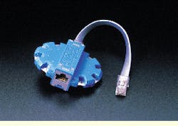
The final device that may be needed in residential or light-commercial testing and troubleshooting is a modular break-out adapter. This device provides a convenient way to clip onto the individual pins of any 6- or 8-position modular jack or plug. Various styles of adapters exist; some break all leads of the jack out into flat conductors that alligator clips can be connected to, while others have a means of switching between pairs.
Rough-in wiring tests
Never begin installation of telephone wiring or devices on a roughed-in job until the rough-in wiring has been tested for shorts, grounds, and opens. If you begin with a verified rough-in telephone wiring system, it is possible to detect a fault in device wiring at the time the error is made. In this way, if installation of the device is completed and a problem shows up, it is likely that the fault lies in the device termination rather than in the building wiring.
Failure to install proper wiring and devices before occupancy can also cause serious disagreements and lead to a dissatisfied builder or homeowner. These problems often arise when the occupant requests additional lines from the exchange carrier, only to be told the wiring is inadequate or defective. You can avoid these disputes by using the proper materials and test methods in the first place.
Some sophistication is required when you are troubleshooting telephone wiring systems, because there are many ways that problems can arise if the multicolored, color-coded conductors are not properly matched and devices are not correctly wired. Polarity must always be observed, especially when making the transition from one color code to another. Most electrical house-wiring problems show up immediately with a blown fuse or activated circuit breaker, but many telephone wiring system problems do not show up immediately.
The best choice of wire for residential and light-commercial applications is four-twisted-pair jacketed inside wire that is listed by Underwriters Laboratories (UL--Northbrook, IL) and compliant with Article 800 of the National Electrical Code. Quad wire--in which the pairs are not individually twisted--generally is not suitable for these applications because it is only designed to carry one analog voice circuit. The other two wires are for ground and accessory functions. Quad wire especially should not be used for multiple lines, key system, private branch exchange systems, digital phone sets, or data applications.
The basic testing procedures for these types of installations include
- basic testing before trim-out
- using a residential-style battery and volt-ohmmeter
- using a specialized continuity tester
- using a tone generator and inductive probe
- testing for shorts and opens (or continuity)
- testing for crosses
- testing for splits
- testing for reversed polarity (or rolls)
- final verification testing.
These tests should be performed on each wire pair, but first make sure that the system is not connected to the network. Pull the plug at the demarcation point first, or more accurately, do not connect to the network before completely installing and testing all components. In commercial installations, test horizontal cable runs before crossconnecting at the telecommunications closet--if one is present.
Testing procedures
Before using any test equipment, visually inspect wire color-matching to ensure that the right access line is assigned to the right set of pairs. Ensure that the tip (positive) and ring (negative) are assigned to the proper pins. You are now ready to test each pair for continuity, shorts to ground, shorts to other pairs (also called crosses), and reversed polarity (or roll).
At each outlet, test each pair with the volt-ohmmeter. Verify that the polarity of each pair is correct, with the tip at positive voltage and the ring at negative. Also, verify that no continuity with any other pair is present at the outlet. You do this by checking the tip lead against all other leads and then checking the ring lead against all other leads.
A specialized continuity tester also can be used to check for shorts, opens, and polarity reversals. On such devices, one or more light-emitting diodes (leds) signal problems. The tester provides battery voltage for the test; if a short exists, the appropriate led will light.
If the continuity tester has been used to verify continuity, polarity, and lack of shorts, and yet a fault still exists, a tone generator and inductive probe can be used to find the location of the fault or to identify the path of the faulty wire pair so that it can be spliced for a new circuit. The tone generator is attached to one end of a vacant pair to be traced, and the probe is used to pick up the tone, tracing the signal along the wire or finding it at the other end.
Once the toner is connected to the leads at the outlet, take the probe to the distribution device or telecommunications closet and listen for tone. When the probe is held near the pair carrying tone, the tone will be strong. (It is normal for lesser volume to be picked up on adjacent leads or pairs.) The pair carrying tone can be verified by touching the tip of the probe across the leads. The tones will cease if that pair is the one carrying the signal.
If the continuity tests showed no faults, the leads are normally punched down in commercial applications. In residential installations, they may have already been terminated at the distribution device.
With the toner still at the outlet, a butt set can now be connected across the pair. The impedance of the butt set provides additional information on the circuit. It should pick up the tone, and the tone should be relatively loud. If the tone is faint, an open, or break, in the circuit is likely; if the tone is not heard at all, the likely fault is a short.
In commercial installations, an earth ground point is available in the telecommunications closet. Test for shorts to ground by attaching one lead of a continuity tester to that ground and running the other lead down the clips of the punchdown block, if they are accessible. In this way, testing for shorts to ground can be done after the leads are terminated.
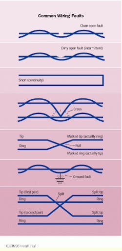
The continuity setting of the tone test set is used to locate shorts and verify continuity, or absence of opens. A full short is indicated with a continuously lit led, while a resistive or dirty open condition is indicated by a dim or blinking led.
A cross is a common fault caused by sloppy device wiring. It allows a short to develop between two terminals. The problem usually occurs because too much bare copper conductor is stripped and the tail is not trimmed following connection. Testing for crosses involves using the continuity mode of the toner to locate an electrical path from either conductor of one pair to either side of another pair.
A split occurs when two wires of a pair are split, or separated, and improperly matched with wires from another pair. For example, the tip lead of pair #1 is mated with the ring lead of pair #2. A split will normally be located during tests for opens and continuity. Splits most often occur during splicing operations in low light or when the installer is tired or distracted. Splits can be isolated using the tone test set and inductive probe or the tone test set with the lineman`s test set.
Testing for reversed polarity
A reversed or rolled pair results when the tip and ring leads are reversed in connecting to the network. This may be done while splicing or installing a device. Proper polarity is essential if some tone dials are to operate, but a roll will not affect rotary dialing.
If a true tone telephone set does not produce tone beeps when the keypad is pushed, polarity may be reversed. If changing the polarity causes the set to beep as the keys are pushed but the numbers are not dialed--that is, the dial tone stays on--then the central office is not equipped to provide touch dialing on that particular line. Some service providers charge a monthly fee to provide touch-dialing capability on a line; if the fee is not paid, the telephone company may inhibit tone dialing electronically.
If a push-button set produces dial pulses rather than tones when the keypad is operated, the telephone is not really a tone set. Although called a universal dialing set, it does not signal to the central office with tones; the numbers are pulsed out just as they are with a standard rotary-dial phone. This type of set is easily identified by the letters "te-r" (for Terminal Equipment--Rotary) at the end of the Federal Communications Commission registration number printed on a label attached to the telephone. If the last three letters on the set are "te-t" (for Terminal Equipment--Tone), then the device is a true tone set.
If dial tone is connected to a pair under test, the presence of a roll can be detected using a tone test set. Some installers prefer to test polarity with a butt set and tone test set, without the dial tone being connected. There are several methods that will work to do this. It is also possible to use a 12-volt lantern battery as the source.
If you discover that a pair has been rolled on the network side, report the problem to the utility. Do not reverse the inside wiring to accommodate a network reversal. The network error may be detected and corrected at any time, reversing your inside connection and leading to a callback.
Final verification testing
After the jack has been installed in the outlet, and assuming that all prior tests have been successful, final verification testing can be performed using a telephone set or butt set, assuming that dial-tone service has been installed. Splitting adapters can be used when needed to test for multiline service.
After connecting to the network interface device at the demarcation point, go off-hook to receive dial tone. If a test number is available, make a call to it and receive a return call. Check with the local telephone company if you are unsure about test lines. Your office may be able to assist if a test number is not available.
Listen for clear transmission without pops, clicks, or scratching sounds. Make sure that digits dialed will stop dial tone and that dial tone resumes when the phone is hung up and then taken off-hook again.
If these tests fail, either the line has not been properly installed, or the fault is in the access lines to the telephone company. In the latter case, the company should be contacted immediately to avoid call back. If the fault is not with the outside lines, repeat your tests for each of the lines at the demarcation point. If you find a failure on one of the lines, check the connections to the jack and inspect the wiring, including the distribution device and any auxiliary disconnects. Some phones may not work with polarity reversed, so be particularly careful to check wire colors for proper polarity.
If dial-tone service is not available, perform the same tests as for rough-in before the jacks were installed. A splitting adapter may be needed to test each line of each jack. A toner may be used with a normal telephone set or butt set to test for dial tone. Most toners provide an audible tone to the phone as well as sufficient voltage to power the phone to generate touch-tone or rotary-dial digits.
Michael Shatzkin, residential marketing manager at Leviton Telcom (Bothell, WA), has been associated the past 11 years with the "soup to nuts" of cabling products, from basic jacks to Category 5 and data-communications equipment.
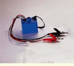
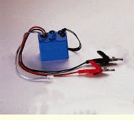
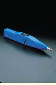
The tone test set (top) and inductive probe are used together to identify where particular wires are located, broken, or terminated--even through drywall or within large cable bundles. The test set generates a tone, and the probe detects it and identifies the wire carrying it.
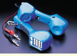
Sometimes used instead of a probe, the lineman`s test set--also called a butt set--allows bridging onto wire pairs for monitoring or dialing.
The most common problems occurring in residential and light-commercial wiring systems range from clean open faults to ground faults.
The modular adapter is another troubleshooting device. It can break out all leads of the jack into flat conductors or switch between pairs.
A word of caution
Disconnect electrical sources, if at all possible, before performing these tests, which are not intended to be performed on energized wiring or circuits. In the event that telecommunications wiring has come in contact with power circuits, severe shock is possible. Check with a qualified electrician if you`re uncertain of your installation`s wiring status or unfamiliar with electrical wiring. Also, check local electrical codes and other requirements before working on electrical or communications wiring circuits.
