Patrick McLaughlin
Manufacturers look for higher speed without sacrificing easy installation.
In the telecommunications closet (TC), which serves as the central nervous system of a premises communications network, numbers take on a significance that is not always apparent. While it is easy to see the numbers printed on labels and affixed to patch panels and other termination equipment, it is the "unseen" numbers--those that can be viewed only by using specialized test equipment--that tell the real story of network performance. And, as network administrators consider implementing a tenfold--or even a hundredfold--increase in speed, to as much as 1 gigabit per second, these unseen numbers, according to standards-makers, will determine whether or not such leaps in network transmission capability are possible.
The unseen numbers are measurements of the electrical performance of the cable and connectivity components of the cabling system. One such connectivity component is the connecting block. The performance characteristics of connecting blocks, along with the other parts of the cabling system, are currently being scrutinized by the 802.3 AB committee of the Institute of Electrical and Electronics Engineers (ieee--New York), which is working on a Gigabit Ethernet standard.
Connecting blocks provide an insulation displacement connection (idc), so they are often referred to as idc blocks. In an idc termination, the insulation around a conductor is cut, and the exposed conductor directly meets the block`s metal contact, forming a gas-tight connection. The termination, called a punchdown, calls for the cable installer to separate the wires in a cable, placing each wire against a contact on the block and then, using a punchdown tool, to press the wires against the contacts. Depending on the type of tool they use, installers can make terminations in one- to ten-wire increments.
Four types of blocks
Four main types of idc blocks are offered on the market: Two are considered universal solutions, and two are proprietary.
The two universal solutions are 66 and 110 blocks. "The 66 block was really the 110 block`s predecessor," says John Siemon, vice president of engineering at The Siemon Co. (Watertown, CT), "and was the first widely used insulation displacement technology for telephony purposes. The contacts are accessible from the front of the block. Wires are laced in from either side and are punched down. Installers really like the 66 block because of its versatility and the fact that it is robust and easy to use. These advantages help to explain the continued demand we see for 66 blocks, even though the original design is several decades old." He adds that the accessibility may be undesirable to some because the 66 block does not offer what he calls a "quiet front." For this reason, Siemon recommends that covers be used for additional protection.
Siemon contrasts the 66 block with the 110 block, saying, "The 110 block has a base and a connecting block. One idc is at the bottom, and at the top is a very similar contact. So it looks double-ended. The termination on the bottom is done by inserting the block onto the base, and on the top, the installer can lace wires into place and use the termination tool."
Generally speaking, the technology of the 110 block outperforms that of the 66 block, according to Siemon. He adds, "And not all 66 blocks perform the same. It`s an extremely versatile technology. You can have a 66-block clip configuration with the capacity to connect a given pair to as many as seven different circuits. This capability is commonly used for telephone service, where one trunk line is connected to multiple outlets. Even though a configuration that provides multiple connections to the same circuit is not `structured cabling` and will not deliver sufficient channel performance to support most local area network technologies, there are still many pots [plain old telephone service] installations where this type of arrangement is used. In a 66-block implementation with a one-to-one ratio of incoming and outgoing connections, without bridging, the performance is relatively close to that of a 110." The 110 block, he adds, is not designed to accommodate a single feed wire and multiple distribution wires. "The 110 contact is limited to a one-to-one ratio of incoming to outgoing wires."
Ken Metz, a cabling installer with Teldata Systems Inc. (Seattle, WA), prefers 110 blocks. "I find 110 blocks faster and more efficient than 66 blocks," he says. "The 110 block is easier to get your fingers into." He comments, however, that the choice of which to use is often application-driven. "If an installation has exclusively used 66 blocks in the past, I`m going to use 66 blocks again," he notes. "One reason is that the 110 and the 66 blocks require different tools. If I`m using both 110 and 66 blocks in the same installation, I need two different tools."
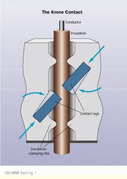
Krone (Englewood, CO) produces several models of the Krone block, which is proprietary in design. On a Krone block, the two contacts to which an individual conductor is terminated are positioned at 45o angles from each other. This positioning, Krone says, leaves more wire between contact points and provides a more stress-resistant connection.
The bix block is a proprietary solution from nordx/cdt, a subsidiary of Cable Design Technologies (Pointe-Claire, QC, Canada), which recently began producing 110 blocks as well. "Both bix and 110 products have the same function," says Bernard Chevarie, product manager for copper connectivity with nordx/cdt. "However, they differ in design--the way the clips are encapsulated in the plastic housing--and in installation procedure. The bix connector itself is a one-piece symmetrical 25-pair connector assembly with a fully enclosed clip. That is the most visible difference. The 110 crossconnection system is a two-piece construction." He explains that a 110 crossconnection system includes a wiring block and a connecting block, and the bottom portions of the clips are exposed before termination.
"Another difference is that the bix has a geometry that puts more distance between two adjacent contacts," adds Chevarie, "which gives the bix an advantage in terms of near-end crosstalk performance."
"The differences among the types of blocks boil down to density and footprint," says Peter Newman, marketing manager with Leviton Telcom (Bothell, WA). "Density means how many connections you can make per square inch. The blocks vary, with bix and 110 blocks having higher densities than 66 blocks. If you spread the contacts out farther, you will get higher performance and lower density."
Enter the patch panel
Patch panels fill the same need as idc blocks--connecting network equipment such as hubs to workstations. However, patch panels are said to offer users more flexibility, particularly with network moves, adds, and changes. Installers and technicians terminate cables to a patch panel by putting modular plugs onto the cables, then plugging into the panel. This offers easy plug/unplug network technology changes, whereas changes in a network with idc blocks require tearing out and repunching wires.
Other factors can also affect the choice of one technology over another. "Both blocks and patch panels serve the same purpose, but can be used for different applications," Newman explains. "Sometimes it`s a matter of how the room is laid out. If you have room on the wall but not the floor, you`re likely to use blocks because they`re wall-mounted. If you have more room on the floor than on the wall, you`re likely to use patch panels because they`re rack-mounted."
Newman adds that patch panels offer aesthetic advantages to some customers. "They have cable management built into them and make an installation look high-tech. Blocks don`t look too high-tech. So user preference probably comes into play." Cost and performance also factor into a purchasing decision, he says. Blocks are generally less expensive than patch panels, but in terms of performance, "there isn`t a big difference," Newman states. "We`ve tested both extensively and found that on a performance basis, they`re more or less the same, at least for Category 5 and enhanced Category 5 technology."
"You can certainly use connecting blocks for high-speed data," John Siemon says. "The symmetry of the pairs plays a role. With a connecting block, you have four pairs side-by-side. When you are using patch panels, the configuration of the modular patch panels gives you a split pair in the center. That introduces some inherent imbalance, causing crosstalk and other performance deficiencies that have to be overcome using compensation techniques. That inherent disadvantage does not occur with a 110 or any other connecting block because the pairs are not split."
Still, Teldata`s Metz claims that many customers prefer the modularity of patch panels. "Panels give the customer the option of patching, which most appreciate. If a customer wants to make a network change and he has blocks instead of patch panels, he will either have to use a punchdown tool to make the change or call in a technician for a service call. Many times the customer doesn`t bother making the change because of that."
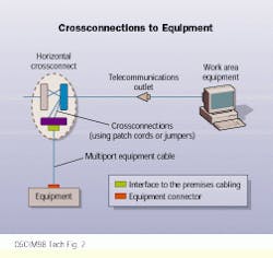
Regardless of whether a network relies on patch panels or idc blocks in the TC, the choice of whether to use a crossconnection or an interconnection can still affect overall system performance. nordx/cdt`s Chevarie explains that a crossconnection system has an additional connection point, which an interconnection system does not need. In a crossconnection scenario, the cabling from the network equipment is terminated to one block or patch panel. The cabling that runs from the TC to the workstation outlets is connected to a different block or patch panel. Then the two connection devices are connected to each other.
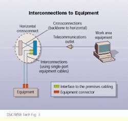
In an interconnection, Chevarie continues, a single connection point links the equipment and the distribution field. In the case of a patch panel, the distribution cabling is punched down to the back of the panel while the equipment cords connect to the panel`s front. The interconnection scenario, with one fewer connection interface, performs better.
"Crossconnections have historically been the preferred layout in TCs because they have given more flexibility," he notes. "But that is not really true anymore. Most equipment hubs are now equipped with 8-pin modular connectors, so the extra field in a crossconnection system is not necessary. The crossconnection is not as desirable as it once was."
The high-speed test
The use of a crossconnection versus an interconnection may be significant for a network administrator who wants to run Gigabit Ethernet, says Leviton Telcom`s Newman. He says that members of the ieee committee developing the Gigabit Ethernet standard "made some assumptions about architecture" when establishing acceptable performance parameters for the installed base of Category 5 cabling systems. "They assumed, for instance, that most current installations have an interconnection in the closet, which means one connection point. However, those that have crossconnections in the TC have an extra connection that may not be budgeted for." (See related information about crossconnections and interconnections in "Ask Donna," page 10.)
If architecture might affect a current network`s ability to handle gigabit-speed traffic, will the installed base of components also affect that ability? "People need to be reminded that the Gigabit Ethernet project is still targeting Category 5," answers John Siemon. "The 110 block is suitable for applications such as Gigabit Ethernet, and so is the 66 block, which was redesigned in the early 1990s to satisfy Category 5 requirements."
"Currently, block-based systems are data-compliant," says Brian Reed, senior product manager with connectivity-component manufacturer mod-tap (Harvard, MA). "But block-based systems are typically not used for data applications. Traditionally, they have been used for voice, and many still think of them as voice products.
"Actually," Reed adds, "it is more difficult for a manufacturer to attain higher data rates with a patch-panel crossconnection than with a block-based crossconnection system. A weak link in a patch panel is the modular jack since the contacts are very close to each other and they bleed signals from one contact to another. One advantage idc connectors have is that the contacts are spaced three to four times farther apart, so crosstalk is not as much of a problem. Patch panels became popular because of ease of use," he concludes, "not because they were any better at transmission than the block-based system."
"I think that many patch panels on the market now will be able to handle Gigabit Ethernet when it`s released," Siemon says, but the Telecommunications Industry Association (tia--Arlington, VA) and other standards bodies have identified performance issues not addressed in the tia/eia-568a Commercial Building Telecommunications Cabling Standard. While these issues do not significantly impact Category 5 systems transmitting 100 megabits per second, they probably will impact the same system`s ability to transmit 1 Gbit/sec.
"Most notable is far-end crosstalk performance," Siemon continues. "Far-end crosstalk hadn`t been looked at by standards bodies because it was not important to applications such as Fast Ethernet. But with Gigabit Ethernet, which uses full bidirectional signaling, we have looked at far-end crosstalk and found that the compensation technologies used in patch panels to achieve Category 5 performance sometimes cause performance degradation in terms of far-end crosstalk. So it is possible that there are Category 5-compliant products sold now that will not meet the anticipated requirements for Gigabit Ethernet. tia groups are now working to bridge the gap between tia/eia-568a and the additional specifications needed to support gigabit transmission."
Siemon states that test-equipment manufacturers are also involved in the gap-filling process and that introductions are being made that allow field verification of far-end crosstalk for installed cabling. He emphasizes, however, that singling out the performance of patch panels is short-sighted. "Once a patch panel is connected to a cable and that cable is connected to an outlet, it becomes a different entity. It`s a system. It`s cabling. And cabling-system performance is what really matters." Siemon claims that extensive research ensures that the vast majority of existing Category 5 installations will support the requirements of the coming specification.
It is uncertain whether or not patch panels are more prone to far-end crosstalk anomalies than are blocks, says Leviton Telcom`s Newman. "The 110 block might not have as bad a far-end crosstalk reading as the typical patch panel because the block is smaller. But there is a lot of debate about how to measure far-end crosstalk, about exactly what you are measuring when you do measure it, and about what the quantifiable number for the component really needs to be in order to get good performance. The only sure thing right now is that there is no agreement on anything."
Return-loss measurements
Sterling Vaden, vice president of research and development at Superior Modular Products (Swannanoa, NC), agrees with Siemon that handling Gigabit Ethernet impacts the entire system. "I think the whole system will be put to the test," he says. He adds that in addition to far-end crosstalk, return loss is another performance characteristic that will impact Gigabit Ethernet transmission, even though it does not substantially affect 100-Mbit/sec Fast Ethernet. Return loss, he explains, involves "reflected signal energy that bounces off the connector and is reflected back to the signal source. So the worse the return loss is, the more energy gets reflected back." Vaden states that return-loss measurements typically get worse as the transmission frequency increases.
"Return-loss measurements on a channel that includes worst-case connectors and worst-case cables that still comply with tia/eia-568a do not add up very well," Vaden continues. "There are a number of different ways to model channel return loss, so actual measurements haven`t been made yet. But it looks like the installed base of Category 5 cabling should probably be tested to see if the channels can handle Gigabit Ethernet." He comments that employing interconnections instead of crossconnections can help improve return-loss performance if connecting blocks have marginal performance.
New system standards
A working group within the tia is currently developing two new cabling standards--one for enhanced Category 5 cabling and another for Category 6. While some questions still remain about Gigabit Ethernet running over some existing Category 5 systems, Superior Modular Products` Vaden asserts that any system meeting the impending enhanced Category 5 standard will, without question, accommodate 1 Gbit/sec. Even though figures are not yet definite, Vaden says, "The proposed enhanced Category 5 parameter for return loss will be 18 decibels at 100 megahertz. And for far-end crosstalk for connectors, the standard will specify 35 dB at 100 MHz. Those numbers should meet the minimum channel-performance requirements for Gigabit Ethernet."
He says that these oncoming requirements will not affect his company`s products. "The far-end crosstalk on almost all of our connectors is better than 40 dB at 100 MHz. So we`ve had a good margin all along." He says, however, that specifiers of products may not warmly receive a marketing message that says, "Our old products are good enough." To that end, he states that Superior Modular is redesigning some existing products so that they exceed the forthcoming standard requirements.
"The performance of connecting hardware is almost entirely determined by design," Vaden notes. "Most patch panels use circuit boards to connect the input to the output. The way you design that circuit board is critical to the performance of the hardware as a whole. You can adjust that performance by making incremental changes in the design.
"Some claims about Category 6 performance are based on tuning the connecting hardware to a different patch-cable performance," he continues. "There is not much change in the actual physical design of the connectors, but there is significant change in the electrical design."
He comments that his company is specifically targeting return-loss performance in its new designs. "Return loss is going to play a major role because as data rates and frequencies go up, return loss becomes much more important for good connector performance."
He says that other precise design techniques allow a manufacturer "to tune a patch panel to work with a modular patch cord that has a certain characteristic." On the other hand, says nordx/cdt`s Chevarie, when connecting blocks are used, the patch cords--not the connector--get fine-tuned. "You do not have to modify a bix connector to achieve higher performance," he says. "If you use a patch cord at the connecting block, the patch cord must be modified. So we are now developing patch cords that will meet enhanced Category 5 performance."
"The same is true with a 110 block," Chevarie says, "except that if you use a modular plug with a 110 block, more compensation is necessary in the patch cord."
Despite this necessary compensation, Teldata`s Metz says, "110 blocks with patch cords work very well. They allow the same modularity as patch panels."
The Siemon Co. is currently developing a next-generation connecting block, which it will call the 210 block. "It is modeled after the 110 footprint and uses some of the same design principles, but has better performance," John Siemon reports. "The contact spacing and some other design aspects have been refined."
He says that the 210 block is being introduced in anticipation of the Category 6 cabling standards. "The objective is to make sure that the connecting hardware does not have too detrimental an effect on cable performance. To do that, the industry must keep pace with both cable and connecting hardware. Category 6 performance requirements will be the next logical step toward satisfying the ever-growing demand for bandwidth to the desk."
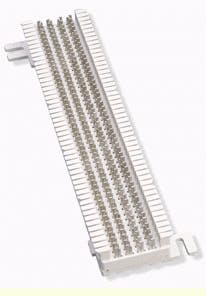
The 66 block, originally designed and still widely used for voice applications, contains contacts that are easily accessible from the block`s front.
This diagram, drawn from information provided by Krone, shows the effect of Krone contacts on a wire. Insulation-clamping ribs hold the wire securely and isolate the contact area from vibration and mechanical stress, while contact tags at 45o angles across the axis of the wire make a gas-tight connection.
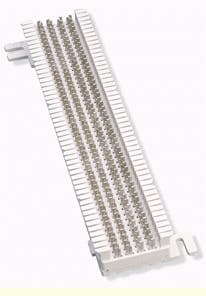
Some technicians find the 110 block easier to use than the 66 block because of easy accessibility.
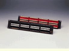
Patch panels, which have been lauded for the flexibility they provide end-users, do not resemble connecting blocks, but perform the same basic function: connecting network-equipment cabling to distribution cabling.
In a crossconnection, network-equipment cable is terminated to one connecting device and distribution cabling is terminated to another connecting device. The two connecting devices are then joined using patch cords or jumper wires.
An interconnection includes one connecting device, to which both network-equipment cables and distribution cables are terminated. Because connection points are sources of signal loss, a network will achieve better performance by employing an interconnection instead of a crossconnection.
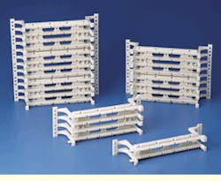
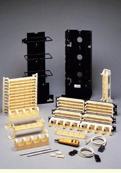
This line of 110-connection products from Leviton Telcom includes a punchdown tool and both wall- and rack-mount connecting blocks.
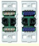
Shown here are the 110 insulation displacement connection (idc) connector (left) and the bix idc connector (right) manufactured by nordx/cdt. While both perform the same function and look similar, the workmanship involved in terminating cables to each differs.
