Overview of support systems for cable and equipment
Compare features of copper-cable support systems before specifying one type for an application.
Bob Crain
B-Line Systems Inc.
The support system for cabling and equipment is a vital component of a properly designed data-communications system. The acceptance and use of the eia/tia-569 Commercial Building Standard for Telecommunications Pathways and Spaces by architects and engineers has proven the importance of a carefully designed and maintained cable-support system. There are six major types of cable supports: cable runway, center-rail systems, cable tray, wire basket, bridle rings or cable hooks, and wireway. Each is designed for specific purposes.
One of the most important yet overlooked aspects of a network designer`s job is the specification of a cable-support system. Specifying the requirements of the design can be a difficult process. It may be helpful to consider six key areas when specifying a cable-support system:
load capacity
grounding requirements
materials
finishes
amount of mechanical protection required
plenum requirements
Load capacity
The maximum cable load allowed on the system is called the load capacity. Span (the distance between supports) and load (the maximum cable weight) dictate the load capacity of a cable-support system. Different standards may use different terms when referring to load capacity but it all boils down to span and cable weight.
Although load capacity can be measured in various ways, the most common methods are based on standards produced by Telcordia Technologies, the National Electrical Manufacturers` Association (NEMA), and the National Electrical Code (NEC).
The Telcordia standard was designed for cable runway, limiting a span to 5 feet in most cases, but allowing 6-foot spans in certain exceptional cases. The standard refers to cable fill as pile-up, which changes according to runway width. For example, for runway that is 6 to 12 inches wide, the maximum cable fill is the width of the runway. For 15- to 25-inch-wide runway, the maximum fill is 12 inches, and for 30-inch wide runway, the maximum fill is 10 inches. Pile-up is limited to minimize damage to cables at the bottom of the stack, which can be crushed against rung supports. For high-performance cables such as Category 5, 6 inches of cable fill is a more realistic specification.
NEMA`s VE-1 standard permits spans of 8, 12, 16, and 20 feet. Permitting longer spans means fewer supports are required, which can lower installed costs. Loading is spelled out in pounds per foot. Cable fill or fill depth can be 3, 4, 5, or 6 inches. In the data-communications market, 6 inches is usually preferred due to tight space restraints on tray width.
NEMA-based load and span designations, called class designations, are as follows:
Load class A is 50 lbs/ft.
Load class B is 75 lbs/ft.
Load class C is 100 lbs/ft.
There are 12 classes under the NEMA designation system. For example, a 20-foot support span with a 100-lb/ft maximum load capacity uses the designation 20C. This rating is widely used in industrial applications to specify cable-support systems.
The NEC addresses cable fill but gives no span limitations. Cable fill for communications cable is limited to 50%, but that does not mean the cable tray is only half full. Rather, the fill is based on the cross-sectional area of the cable. The space between cables will take up the other 50% of the space. A good rule of thumb for determining when the tray is full is the following: the number of cables x the diameter of the cable x 2. Remember that 50% fill is full.
Grounding is also important. Underwriters Laboratories (UL) and the NEC have specific requirements to ensure metallic systems are properly grounded, whether power conductors are present. A system that is grounded--even though it contains only data-communications wiring--must be capable of carrying away (grounding) accidental power sources or surges.
Another important consideration is material. Steel is cost- effective but heavy. Aluminum is more expensive but easy to work with, lightweight, and aesthetically pleasing without having to be coated with additional finishes. Nonmetallic materials can be expensive but are lightweight and easy to work with. However, they can be hazardous in plenum spaces because of the smoke and fumes they emit in a fire.
Finishes offer protection
There are three types of finishes: painted, zinc-plated, and polyvinyl chloride (PVC). Painted finishes offer satisfactory protection against corrosion but do not offer grounding protection. Zinc-plated finishes are impervious to corrosion and offer grounding and static protection. PVC, an anodized finish, offers both corrosion resistance and grounding.
When specifying a finish, consider its thickness, adhesion properties, and corrosion resistance. A minimum thickness for the coating is 1.5 mil for paint and 0.5 mil for zinc plating. These thicknesses provide good performance indoors over the life of the product. For adhesion, specify conformance to test results ASTM D33594D, as a minimum. This test tells how well a surface has been cleaned and how many years the paint will last before peeling. For a 20-year lifespan indoors, specify corrosion resistance ASTM B117, 400 hours.
Consider also the mechanical protection that the cable- support system should provide. Rung support is acceptable for larger-diameter cables. A solid bottom is better for small- diameter cables because it has a larger cable-bearing area. Covers are required only if items will drop on the cables and damage them, which is unlikely. A minimum bend radius of 3 inches is needed to maintain cable performance. Most cable-support systems allow for this, but even in the most carefully designed system, cables may still be abused during installation.
When to use plenum cable
NEC section 300-22 defines three types of plenum areas:
Class 1, division 2--in such areas, explosions are possible, so no wiring is allowed
Environmental air plenum, in which raceway is acceptable
Other space used for environmental air. In these spaces, raceway, wireways, and solid-bottom trays with covers underfloor and return air are acceptable.
Not all areas above or below are used for environmental air--they could be just dead open space. Find out!
Plenum cable can be used only in environmental air-handling areas. If used in these areas, it must be supported in an open cable-support system such as cable runway, center rail, and ladder-type cable tray. In a closed system, such as raceway, wireway, or solid-bottom tray with solid covers, plenum cable is not required by the NEC.
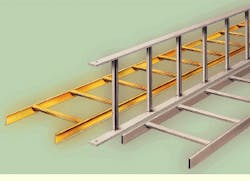
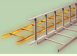
Cable runway
The three basic styles of cable runway are solid bar, tubular, and C-channel. Solid bar is heavy, expensive, and strong. Tubular is easy to install and moderate in price. C-channel is much stronger than tubular, weighs half as much as solid bar, and offers the best balance of load capacity versus weight. It also offers the best price-to-performance ratio and is Telcordia`s preferred runway.
All three styles of cable runway are available in heights of 1 1/2 or 2 inches, with width ranging from 4 to 30 inches. The most popular width is 12 inches.
Since cable runway comes only in steel, there are only two finish options: paint and zinc-plated. Painted runway is usually gray, but it is important to consider how it was painted as well as its test results based on ASTM performance criteria. Remember to specify runway using the performance-based criteria, including MIL thickness, adhesion tests, and salt-spray testing.
The type of coating is not as important. Powder coat is a good, tough coating if cleaned properly. Wet coat is environmentally unsatisfactory. Electrodeposited coating (used by the automotive industry) can be the best because it undergoes a very controlled cleaning stage but is not used as often due to high capital-equipment costs.
Zinc plating is the next finish option and actually a better finish for runway. It is more corrosion-resistant than paint. Furthermore, it is UL-certified as a grounding conductor, whereas paint is an insulator. That means you must scrape paint to attach a grounding conductor. If you specify zinc-plated runway, ground straps are not required by UL.
Gray-painted runway subjected to salt-spray tests shows rusting after 500 hours, but zinc-plated runway subjected to the same tests exhibits no rust at all. Considering the corrosion resistance of zinc plating and the fact that it is UL-classified as a ground conductor, it is clear that zinc-plated runway is a better product.
Center-rail support systems
A relative newcomer to the scene is a cable-support system with a single support rail in the middle instead of one on each side. The main advantage of this design is that there are no obstructions to the cable-fill area. Center-rail systems are available as rod-mounted data-track and verti-rack as well as wall-mounted half-rack and multitier half-rack.
NEMA specifies fill capacities for center-rail supports at 3, 4, 5, and 6 inches deep and up to 24 inches wide. The load capacity for a center-rail system is NEMA 12C--100 lbs/ft over a 12-foot span--which is more than enough to handle 600 Category 5 4-pair cables. A 12-foot span uses fewer than half as many supports as Telcordia requires, which equates to lower installed costs. Center-rail systems are UL-classified as equipment grounding, so they require no additional ground straps. Because these systems are aluminum, they are lightweight, strong, and aesthetically pleasing. They`re also easy to modify in the field.
Center-rail support systems are designed for easy cable installation. The cables can simply be laid in from the side of the support rather than being pulled in, which is an advantage for maintenance, too. Some contractor rate studies estimate that it takes 60% less time to install cable in a center-rail system than in a standard two-siderail support system. Cable tray or runway averages 50% lower installed cost than conduit.
Yet another kind of system--cable tray--is available in ladder, vented, and solid styles. Ladder-type is the most common. Because its vents dissipate heat, the vented type is more suitable for power cables. The solid type is becoming more common for data-communications cabling because it offers a lot of support for small-diameter cabling.
There are cable trays available to meet all NEMA requirements, with spans of 8, 12, 16, or 20 feet and loading capacities of 50, 75, or 100 lbs/ft. Longer spans mean fewer supports, which translates to lower installed costs. Trays that meet NEMA specs support 3-, 4-, 5-, or 6-inch fills and widths from 6 to 36 inches.
Cable trays are UL-classified as an equipment grounding conductor, so they require no ground straps. They are available in aluminum, steel, fiberglass, or stainless steel and come with a finish (primarily for indoor applications) or galvanized.
Cable-tray bottom configurations include ladder-type, which is suitable for most needs. But consider flat-bottom trays if you plan to fill them to capacity or if you plan to use high-performance cabling because such cabling requires low stress on cables.
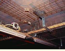
Wire basket
A relatively new style of cable support is wire basket. This welded steel-wire system is available for 1-, 2-, or 4-inch cable fills and comes in 2-, 4-, 6-, 8-, 12-, 18-, and 24-inch widths. Wire basket is available zinc-plated or painted, and its primary advantage is that there is no need to design the system before ordering the components. The unit is similar to runway, in that the installer just cuts and bends the system to fit the requirements and uses splice connectors to make L-, T-, or cross-shaped configurations. It works well for branch runs or unshielded twisted-pair cabling of moderate density. Wire basket is a short-span system requiring supports every 4 to 6 inches for most installations.
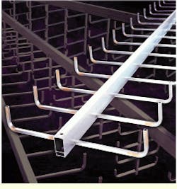
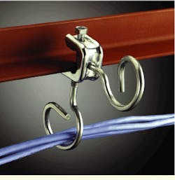
Bridle rings or cable hooks are independent rings or J-shaped hooks attached to structural ceiling members. Typically used for small branch runs, they are available in 1-, 2-, and 4-cable capacities, with a galvanized finish. Because they offer limited support and protection, bridle rings and cable hooks must be placed no further than 4 to 5 inches apart.
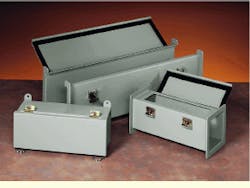
For wireway, also called raceway, the NEC requires 5-foot support spans. The wireway is restricted by a fill capacity that really doesn`t apply because it is based on heat buildup for power cables. The grounding is UL-listed. The device is available in aluminum and steel, and the latter comes with a galvanized or painted finish.
Wireway offers outstanding mechanical protection due to its wraparound metallic construction. Such protection can be useful if you have numerous sensitive cables that need to go from the main office to a remote site or manufacturing plant. Inside the plant is where the cables need the protection.
Equipment support systems
Once the cable reaches the wiring closet, equipment support systems are required as well. Such supports have become as important as cable-support systems in high-performance cabling applications since they not only support the electronics, but also manage the cable. Among the four major types of equipment supports are aluminum relay racks, which are the most common and offer the best price-to-performance ratio for most applications. They offer flexibility for a variety of equipment mounting and easy cable management. Steel relay racks have the same benefits as aluminum but tend to be heavy and awkward to use. Unequal flange racks (also called equipment frames) are heavy-duty and often used by telephone companies. Equipment or electronic cabinets are the fourth kind of system.
An important feature to consider when specifying equipment support is total load capacity, which must be determined from the type and amount of equipment to be supported. Next is thread integrity, which is important for easy installation and proper grounding. The choice between bolted and welded construction depends on the installer`s preference. The choice between floor- or wall-mounted systems is dictated by space limitations and the type of equipment. Choosing between freestanding and overhead-supported systems depends on space and the availability of sufficient overhead structure. Mounting-hole patterns depend on the type of equipment to be mounted. The type of finish is also important, as is ease of installation. The latter is difficult, but possible, to determine if you understand both the products and how they are used. It is an important consideration since the installed cost of a project is the bottom line.
How can you make sure that a rack will meet your requirements, and who can you ask if you`re not sure? Among the people who can provide information to help you with your specification are experienced colleagues, manufacturers, and installers. Trade associations such as BICSI (Tampa, FL) can often answer your questions or refer you to written standards.
To make sure a rack meets your loading requirements, ask the manufacturer for documented load testing. Third-party tests, such as UL, are best. Ask installers about using bolted or welded construction. Chances are they will prefer bolted construction; welded racks are usually too bulky. Talk to installers about wall-mounted racks. Unless space is unavailable, they will likely prefer a floor-mounted rack for its additional cable-management space and the access it provides to all sides of the equipment
Ask colleagues about overhead-supported racks. Most customer-premise sites do not have the necessary overhead structure available.
Make sure you ask or know what your customer`s expectations are when specifying finish. Is the product hidden in a locked closet, or will it be a showpiece behind a wall of glass? A painted or brushed finish can really affect how the installed system looks. The customer`s perception of what the finished product should look like is the key.
Of the two hole patterns available--traditional (1 1/4, 1/2) or universal (5/8, 5/8, 1/2)--you can ask installers or colleagues which they prefer. Chances are they will recommend 5/8, 5/8, 1/2 universal spacing because of the additional mounting locations (units) and flexibility for mounting cable-management products.
Ask the manufacturer to make sure that the rack is deburred inside and outside. A poorly manufactured rack can cut cables and the installer.
Check with the manufacturer or ask the installer about rack packaging to minimize shipping damage. The package should be labeled with the part number and bar code to reduce shipping and receiving errors.
Make it easy on the installer because installed cost is the bottom line. At a minimum, make sure the rack has threaded base holes for simplified assembly, self-squaring design (which is important because, if the rack is not square, equipment will be difficult to mount), and for those times when all else fails, assembly instructions.
Steel relay racks are best-suited for severe-duty applications such as seismic location where mass and strength are a definite plus. Unequal flange racks are heavy-duty racks often preferred by telephone companies or original equipment manufacturers for switches or large-system applications. Electronic cabinets are difficult to wire. They look great but tend to be expensive--four to five times the cost of a relay rack. But when they are completely enclosed with a glass door, they look neat.
This article is based on a presentation made at BICSI (Tampa, FL) and is published with permission.
Cable runway is a traditional means of managing and routing data-communications cable. It is versatile and well-suited for use in areas with high-density cabling.
Cable tray was developed in the electrical industry for cable routing and is becoming more recognized in the data-communications field. Cable tray is widely used in Europe, where more than 80% of all installations are cable tray and less than 20% are conduit. The opposite in true in the United States.
Center-rail systems are relatively new systems that permit cost-effective installation. They are well-suited for hallways such as those in public schools.
Wire basket is also widely used in Europe. It offers the contractor flexibility because it can be modified in the field on the fly, without reengineering the system.
Bridle rings (top) and cable hooks (bottom) provide a simple method of cable support for branch runs or small bundles. Newer-style hooks provide a larger cable-bearing surface than bridle rings--an important feature with today`s category-based cabling systems.
Wireway is another electrical-industry wiring method that offers good mechanical protection in the data-communications market.
Bob Crain is vice president of engineering at B-Line Systems Inc. (Highland, IL). He can be reached at (618) 654-2184 or [email protected].
