The shake on seismic bracing
Tom Rattini
B-Line Systems Inc.
Securing equipment is a growing concern for today`s datacom and telecom cable installer.
Seismic bracing against the wrath of earthquakes is an increasing concern for today`s data-communications and telecommunications cable installer, and efforts to minimize the damage they can do to datacom and telecom infrastructures date back more than 50 years.
Seismic forces are earth-shattering intensities that act primarily horizontally upon the building and its components during an earthquake. The runway or tray and its supports are typically designed with just the gravity weight in mind. During an earthquake, however, there is a certain amount of lateral seismic force to contend with.
Seismic force is based on three factors, the first of which is the seismic zone or the geographical area the project is in. The zone gives us an idea of how big the earthquake and what the expected outcome could be. The other two factors the building code takes into consideration are the building and the system type. Different seismic force values are used in the bracing design, depending on how critical are the building and system.
Given the zone, building, and system type, a designer could refer to the building code and calculate the amount of seismic force for the project. The seismic force can be expressed as a percentage of the weight, which is the same as saying a certain "g-value."
A little history
The 1940 El Centro earthquake in California knocked out telephone systems and was one incident that prompted the development of seismic standards. The strongest recorded quake--a magnitude of 6.9--to strike the Imperial Valley, it caused at least $6 milion in direct damage and was directly responsible for the deaths of eight people and indirectly for several others. At least 20 people were seriously injured.
Bell Labs was an early leader in seismic research, studying and modeling waveforms to simulate and test for earthquake conditions. Now, as Telcordia Technologies--formerly Bellcore--the company has issued a seismic standard for physical protection and also performs testing for equipment manufacturers. Many of the larger telephone companies such as GTE, Pacific Bell, and US West also have developed their own engineering practices for seismic bracing for projects in high-risk areas. And starting in the 1970s, the model building codes added seismic requirements for buildings and building systems. These codes govern customer-premise jobs.
There are two separate sets of rules to think about when discussing seismic considerations for telecommunications applications. The first set includes standards for stand-alone equipment and supports: cabinets and seismically designed racks.
The primary concern with stand-alone equipment is that improperly anchored equipment could overturn or get damaged because of earthquake motions. Suspended systems could also fail. Seismically designed and tested network equipment--as well as the supporting racks and framework that hold this equipment--are available to protect against this hazard. Seismic equipment and its supports provide adequate physical protection to prevent damage during an earthquake. The equipment is dynamically tested to remain functional during and after an earthquake, allowing the phones to stay on and the data networks to continue operating.
The leading test standards for seismic equipment and supports are Telcordia`s GR-63 CORE, "Network Equipment-Building Systems: Physical Protection," and ANSI Standard TI.329, "Network Equipment - Earthquake Resistance."
The ANSI standard was developed largely from the Telcordia document and was a joint effort involving Bellcore, various phone companies, and equipment manufacturers. In either test, the equipment is subjected to simulated earthquake motions on a shake table. It must remain structurally sound and perform its intended function. Separate tests are available for high-risk (Zones 3 and 4) and low-risk (Zones 0, 1, and 2) areas. The seismic zone relates to the potential risk of an earthquake: the likelihood of its occurrence and its magnitude. The lower the seismic zone, the lower the risk of an earthquake. This testing is done for network equipment itself--the switches, computers, and the racks--which must remain structurally sound and perform the intended function.
To adequately protect the telephone system`s integrity, it`s imperative to have seismically designed and qualified equipment as well as supports. Contractors cannot just buy a seismic rack and stick any old equipment in it. The rack will stay together, but the network equipment may shake apart. Conversely, buying seismically rated switches and power supplies and putting them in an ordinary rack may not provide adequate physical protection during an earthquake.
The basic test procedure for seismic racks and cabinets is to mount the rack to a concrete slab with the manufacturer`s hardware, load the rails with dummy weights, and make sure the rack stays within prescribed deflection limits during and after the shake test. This procedure is to make sure the rack will not bang into the wall or adjacent equipment during an earthquake. Proper anchoring as well as the amount of dummy weights plays an important part in the test. The weight on top of the rack is used to simulate the load that a tray might have.
The test is conducted to the Telcordia or ANSI standard, but any accredited lab capable of running the test can perform the testing. The typical attributes of seismic support products are more heavy duty in general with heavier rails and welded construction, and cabinets may have internal bracing
When you`re specifying seismic racks or cabinets, it is important to know what system weight was used in the testing and whether it was a high- or low-risk test. Customer-premises end users and project owners in high-risk areas may specify seismic equipment for critical systems.
The second set of rules includes codes for seismically bracing the cabling systems--runways and the trays running throughout the building. Unlike the network equipment, seismic bracing of building systems, like telecommunications cabling, is primarily a safety concern. Installing braces on tray systems can prevent support failures that are an obvious hazard. Wiring that has fallen can also block egress from the building.
Each job has different types of cabling-support systems: cable trays, wireways, conduit, or hooks. There are different amounts of wiring to contend with and a variety of support methods such as wall or ceiling mounting.
Obviously, it is not possible to bolt the whole system down and conduct a shake test as with seismic racks. Seismic bracing for cabling systems has an entirely different approach. The foremost purpose of bracing a cabling system is to keep it in place and prevent safety hazards that arise during earthquakes. Because the cabling is a building system, the building codes provide seismic bracing requirements.
Building codes
There are three model building codes and code-making bodies: The Uniform Building Code (International Conference of Building Officials), National Building Code (Building Officials and Code Administrators International), and Standard Building Code (Southern Building Code Congress International). Each code is similar in nature and used in a particular region of the country. Each code has a chapter on structural forces for the building itself and the systems within it. This chapter on structural forces also defines the level of seismic force.
Building-code exemptions are another consideration. The project may be exempt from bracing requirements if it is in a very low zone area, has very light cabling loads, or has supports for the cabling system very close to the building structure.
The rules do vary, depending on which code applies and the particular circumstances. Check out the code for specifics. Many exemptions are based on the zone, coupled with the building type. A Zone 2 or 3 small office building may be exempt, but a Zone 2 hospital may not.
Although, historically, seismic bracing has been primarily a West Coast concern, there are other geographic areas where seismic bracing has become an important consideration. For example, the New Madrid fault in southern Missouri is a Zone 3. Contractors and designers should be aware of where their projects take them. If they are designing or installing a copycat project for various parts of the country, they may end up in earthquake country and have to take appropriate measures.
Building-code consolidation
Coinciding with the year 2000 frenzy, the building codes will have their own Y2K event. The three model codes are combining to form one harmonized document, the International Building Code (IBC). The first edition of the IBC is available for adoption in 2000 and has its own section on seismic forces with different values and exemptions. Unfortunately, things are getting more complicated. Soil type and building elevation will be factored into the seismic-force equation. Cabling in the basement will have less stringent values than on the 10th floor, and projects built on less-stable soil will be penalized with higher values. Draft copies of the IBC can be obtained for $10 from any of the code bodies (see "Standards Organization and Building Code," page 57).
The majority of projects must conform to building-code requirements. Therefore, seismic bracing of building systems should at least be a consideration. It is important to investigate possible exemptions. The design engineer may simply reference any of the three codes for seismic-bracing requirements. Since the physical structure itself is designed to meet the seismic-code requirements, the design engineer should be able to provide information about the seismic-force levels that apply for cabling systems.
With the seismic force already identified, the next step is choosing a system to accommodate it. The system must transmit the horizontal seismic force up to the structure or else everything in the building will be flailing around, wreaking more havoc during an earthquake.
For cables or anything else that runs in a line, the seismic force acts in two directions: transverse (perpendicular) and longitudinal (parallel) to the run. Almost any kind of system--runway or tray, wireways, conduits on a trapeze, or hook systems--can be analyzed in this manner.
There are several different ways to accommodate the seismic force and transmit it to the building. Some of the more common bracing assembly components are transverse braces, longitudinal braces, vertical supports or threaded rod stiffeners to keep the rods from buckling during the earthquake, and structural attachments to attach the braces to the building structure.
Longitudinal or transverse braces aren`t necessarily required at every support, depending on how strong the braces are and the amount of seismic force.
For wall-mounted systems like trays or hooks, the horizontal seismic force is transferred to the building directly. As a result, extra bracing is typically not necessary. Simply evaluate the anchors to ensure they are strong enough to take the additional seismic force.
The same rules apply to floor-mounted systems or systems mounted on stanchions. The anchors or stanchions must be analyzed to see if they can take the additional side load without any additional bracing.
Brace materials
Strut is a typical brace material, although angled iron and other structural members are also used. There are two basic brace types: rigid and flexible. Rigid braces can be made from strut, angled iron, channel, or rods, while flexible bracing is typically aircraft cable. The main purpose for using flexible braces is for vibration applications where a rigid brace would directly transfer the vibration to the structure.
Support cables also come in handy if the brace length is very long. Strut and angled iron have limitations on the length that can be used before they would become too long and buckle under the seismic loads. Cables are used in tension only, so they have no maximum brace length. The only downside to this arrangement is that two cables must be used at every brace location.
The amount of slack is important. If the support cable is too tight, it will transmit vibration. If it is too loose, it doesn`t prevent the trapeze from swaying, which is the main purpose of bracing. The cables must be installed in pairs, which keeps at least some of them in tension no matter what direction the seismic force originates.
Structural attachments
Ultimately, since braces must be attached to the building, structural attachments are an important consideration. Different anchors are used for different materials such as concrete, steel, and wood.
The strength of the brace assembly often depends on the number and size of the anchor that is used. The biggest brace in the world is only as strong as the anchor that holds it to the structure. Attachment details and load ratings are available from the bracing manufacturers.
The determination of seismic force and the selection of brace materials and attachments depend on a structural analysis. Calculate those factors carefully because they will determine if your system is adequately braced.
The following rules of thumb can make the task easier for the installer:
The maximum spacing between transverse braces should be kept to 40 feet. Use one or two braces on each braced location (which may be every third or fourth trapeze), depending on the level of seismic force. If braces are spaced too far apart, the tray or other cable support system between the braces can deflect and sway.
Longitudinal braces can be spaced further apart (typically up to 80 feet maximum) because the system is in tension between the braces; it really can`t go anywhere. Put a brace on both ends of the trapeze to keep it from twisting.
To determine the bracing interval, determine the weight of the system in pounds per foot; calculate the horizontal seismic force in pounds per foot (from the building code); determine the strength of the braces and the attachments (this information comes from the manufacturer or engineering professional); divide the brace strength by the seismic force to determine how far apart the braces can be; and check to see if an all-thread rod stiffener is required.
Some manufacturers have tables that complete the process without the calculations.
Whatever the case may be, cabling systems should be analyzed, per building code, to determine if bracing is required and what level of seismic force should be used in the design. The purpose of seismic bracing is to provide secure support of cables so they don`t pose a safety risk for people in the building during an earthquake.
Various manufacturers provide bracing materials and details to help with their projects. Some phone companies may also have details and requirements to follow for their projects.
Seismic racks and cabinets are tested and qualified to withstand seismic forces without additional braces. They`re used to keep critical systems functional before, during, and after the event. Understanding the code basics, equipment standards, and bracing methods, however, will ensure safe and functional installations.
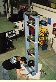
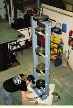
A technician tests a B-Line Systems seismic equipment rack at Telcordia Technologies` earthquake simulation laboratory.
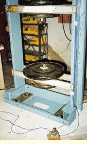
It looks like a plate from the bench press at the local gym, but this weight simulates the bulk of a hub or router.
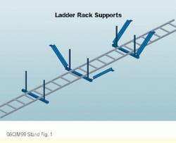
In earthquake-prone areas, ladder rack supports with transverse braces and longitudinal braces attached to ladder racks provide extra support.
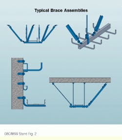
Different types of brace assemblies may be available from the support system manufacturer. Clockwise, starting at top left, are a strut trapeze support, center rail trays, an angled-iron or rod brace, and a wall-mounted system.
Tom Rattini is the sales engineering manager at B-Line Systems Inc. (Highland, IL), a manufacturer of telecommunications, electrical, and mechanical support systems and enclosures. This article is based on a presentation made at the January 1999 BICSI Conference in Orlando, FL.
Standards Organization and Building Code
International Conference of Building Officials
5360 Workman Mill Rd.
Whittier, CA 90601
Tel: (562) 699-0541
Uniform Building Code
Building Officials and Code Administrators International Inc.
4051 W. Flossmoor
Country Club Hills, IL 60478
Tel: (708) 799-2300
National Building Code
Southern Building Code Congress International Inc.
900 Montclair Rd.
Birmingham, AL 35213
Tel: (205) 591-1853
Standard Building Code

