Installation solutions for the jobsite
Frequent problems faced by cable installers spawn new techniques and products.
Ray Keden / ERICO Inc.
One of my most fascinating perspectives on the installation business is that all I have to do to conceive new-product ideas is to go to a jobsite, observe and talk to cabling professionals, find out what their problems are, and then we assemble a design team to solve those problems.
Companies that make cable-pulling, distribution, and routing equipment have taken this approach for product development and problem solving-or at least, they should.
Pulley power
It is no secret that the correct method of pulling data cables is based on two factors: providing a minimum bend radius during and after installation, and observing the maximum pull force for the cable.
When done correctly, pulling cable into a suspended ceiling space is a job for four installers: one on the cable reel, one where the cable enters the ceiling space, one where the cable leaves the ceiling space, and one to pull the cable down at the floor. This four-person crew does not account for someone to facilitate the pulling of cables around corners-not an inexpensive proposition, considering today's hourly rates.
The two installers who are up in the ceiling space are the ones who should be most concerned with the cable's bend radius. And all are responsible for ensuring not to exceed the maximum pull force.
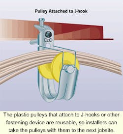
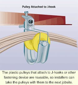
A pulley product that is commercially available can greatly benefit this process, and in fact, can eliminate the need for the two installers who work in the ceiling space. The pulley is a plastic cylinder that turns on a metal pin and attaches to a J-hook. The cylinder and a wire-guide keep the cable bundle within the pulley.
The pulley, connected to any of a number of clamp or clip products, can be attached to the ceiling structure, a substructure, or even the grid of the suspended ceiling. Positioning pulleys in these locations eliminates the need for those two "in-the-ceiling" installers, and the need for a corner facilitator.
Typically, the crew (which now consists of only two installers), can pull bundles in groups of approximately 20 unshielded twisted-pair (UTP) 4-pair cables. After the two installers pull a group of cables, they can spread open the pulleys' wire guides, pull out the metal pins, remove the cylinder, and drop the bundles into the J-hook. They can then re-install the cylinder and pull the next bundle.
Once the installation is complete, the installers can remove the pulley assembly and reuse it with another J-hook of the same size. Meanwhile, the original J-hook stays in the ceiling to permanently support the installed cables. Based on the typical cost of a pulley assembly, and considering its ability to eliminate the need for additional crewmembers on a jobsite, we estimate that a pair of pulleys pays for itself on the first job.
Stabilizing the backbone
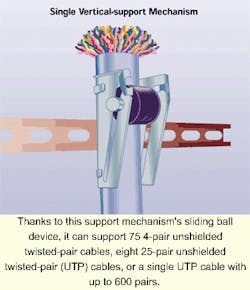
Installers are always challenged to adequately support vertical backbone cables within a building. To avoid pressure points, for example, they must find a way to distribute the support mechanisms' gripping force over the largest possible surface of the cable bundle. In addition, they must support the cables' weight during and after installation, account for the possibility that they may use any number of cable-bundle or cable-diameter sizes, and prepare as well as possible for the addition of cables in the future.
Using the proper supporting mechanisms and a pull-from-the-bottom approach, installers can relieve some of the natural gravitational strain on these riser cables, and accomplish other support and routing requirements.
A key to this technique is to use the correct supporting mechanism. Ideally, you would like a mechanism that is flexible enough to accommodate the various sizes of cables and cable bundles, but at the same time hold the cable firmly in place. If you use a support mechanism made of metal, be sure its edges are not so sharp that they can damage the cables.
Fastener deployment
As for the technique employed, let's assume you are pulling riser cable throughout a 10-story building. Remember, you will use a pull-from-the-bottom method. To begin, pull the cable bundle from the first floor to the third floor. Once there, pull enough slack so the cable can serve all floors. As you pull the cable bundles, pull them through the support mechanism. The mechanism should open so you can pull cables upward, then tighten on the cables when gravity begins to pull them downward.
Once you have enough slack on the third floor to serve all 10 stories, pull the bundle from the third floor to the sixth floor. When you employ this technique, the cables carry a maximum load equal to the weight of three stories' worth of cable weight.
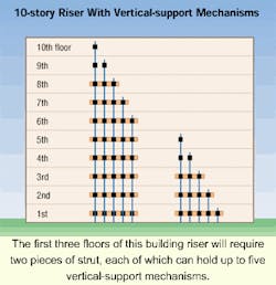
When you are finished, the installed 10-story riser cables will look like this: On the 10th floor, you will have one support mechanism mounted to the wall, supporting the cable inside it. On the ninth story will be two wall-mounted fasteners-one for the cables on the ninth floor and another for the cables that go up to the 10th floor. On the eighth floor, you will have installed a piece of strut and mounted three support fasteners to the strut. If a strut holds up to five fasteners, then the seventh and sixth floors will also have one strut each; the seventh-floor strut will have four support fasteners and the sixth floor will have five fasteners.
Each of the first three floors in the building-which will be the first three that you install because you are using the pull-from-the-bottom method-will require two struts because each strut holds a maximum of five fasteners. The first floor, then, will have 10 fasteners lined up next to each other. You can increase system capacity simply by adding more fasteners.
Faceplates without boxes
Low-voltage faceplates can incorporate data and voice connecting hardware, keypads, and displays, thereby eliminating the need for boxes in stud-wall construction. All you need is a bracket that allows secure attachment of the faceplate to the wall. You can now find designs on the market for new construction, and designs for retrofit installations that use an opening in the drywall between studs.
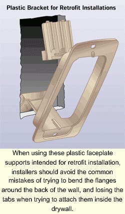
For retrofit jobs, you no longer need to use a screw assembly. Instead, you can use a plastic bracket that incorporates locking tabs into a molded design. To use the bracket, break off the tabs and snap them onto the teeth of the bracket's flanges. The front of the bracket features four dimples; press the bracket against the drywall and connect the dimple impressions to get a template for the wall cutout. Once you cut the hole, squeeze the flanges with the tabs into the hole, and firmly draw the tabs against the drywall.
Installers commonly make two mistakes when using these brackets:
- They try to bend the flanges around the back of the wall; and
- They lose the tabs when trying to attach them inside the drywall.
Unfortunately, the flanges will break if you try to bend them around the back of the wall, and the tabs will not bounce back if you lose them inside the wall. The brackets are available in one, two, three, and four-gang styles.
Time- and labor-saving products that comply with standards, codes, and practical installation requirements always have a future. New solutions appear at every trade show. But it is the cabling team's job to validate these products by trying them out.
Ray Keden, RCDD, is codes and standards manager with ERICO Inc. (Solon, OH). You can reach him via e-mail at [email protected].

