How UTP deals with interference
Even well-insulated cabling sites aren't immune to power interference. Here's one way to avoid trouble.
George Georgevits / Power and Digital Instruments Pty. Ltd.
I have been involved with the design and testing of data-cabling installation of all sorts for more than 10 years, with about 100 sites to my credit. I have designed as well as tested many UTP (unshielded twisted-pair) components for performance verification purposes to 100 MHz and beyond. Sure, I have found problems-the odd component where it did not meet the standards requirements, the odd installation where the rules were bent a little here and there, but I have never come across a well-insulated UTP system on which circuits exhibited problems caused by interference. It simply has not happened.
I have seen cases where the cable has been coiled around fluo rescent lights (not recommended practice-but you can do it for a test) and I have seen situations where the recommended termination techniques were not followed and where power and data cabling were tied together up in the ceiling. I have even seen a case where Cat 3 joiners were used to extend Cat 5 horizontal cabling and then hidden inside the wall-none of these abuses have prevented 10Base-T or telephony circuits from working properly. Mind you, I think it may have been a different story if 100Base-T were involved.

So until now, I thought that if the rules were followed and reasonable quality components were used, you couldn't go wrong. This is the position I espoused at numerous cabling conferences, and with confidence, I might add. Well, my latest experience has changed this steadfast outlook: I must now admit I was wrong!
A quick UTP refresher
Before getting into the details of this latest job, it is worthwhile to quickly review how UTP works and, in particular, why it is normally immune to interference without the use of a shield.
Twisted-pair circuits use two identical conductors twisted together to form a pair. Usually, twisted-pair cables contain more than one circuit, and in 4-pair UTP, each adjacent pair has a different pair twist rate. This is done so that crosstalk between adjacent circuits in the same cable is reduced to an acceptable level.
To gain a high level of immunity from interference, twisted-pair circuits use a form of signal transmission known as balanced-pair transmission. Balanced-pair circuits possess the following attributes:
- The impedance, when measured from each leg to ground, is equal. Thus, both conductors are at signal potential (i.e., above ground potential). Compare this with coaxial, where one conductor-the outer screen-is grounded. Signals in coax are a form of unbalanced transmission.
- The conductors of the pair are driven in "push-pull" or differential mode. This means that the signal at any point along the circuit, when measured from one leg of the pair to ground, is equal in magnitude and opposite in polarity (or phase) to that measured at the same point from the other leg of the pair to ground.
- Any outside electromagnetic field that couples into the cable causes the same voltage (both magnitude and phase) to be induced onto both legs of each pair in the cable. Hence, this induced interference voltage is in common mode.
- Finally, the terminating equipment at each end of the cable is designed to respond only to differential-mode signals, and is designed specifically to reject common-mode signals. Thus, although the twisted-pair cable picks up unwanted signals through coupling, it does so in a form that can be rejected by the terminating equipment.
UTP theory vs. reality
The above describes how UTP works in theory. In real life, however, things are not quite so simple. Small imperfections exist in the structure of all cables. They are created as part of the manufacturing process. The installation handling process introduces further minor deformations (kinks, bends, pinches at cable ties, stretches that occur when pulling through ceiling voids, etc.).
All these add up to pair geometry imperfections, which result in the pairs no longer being perfectly balanced. This, in turn, results in a small part of any common-mode interference signal (which has been picked up by induction) being converted by the cable imbalances into a differential-mode signal. This differential-mode portion of the interference signal adds to the noise on the circuit, as it is now in the same form (differential mode) as the wanted signal, and the circuit terminating electronics can no longer differentiate between it and the wanted signal.
The parameter describing the degree of unbalance of a cable is called longitudinal conversion loss (LCL). It is measured in decibels and represents the fraction of common-mode signal converted to transverse mode. For example, an LCL of 40 dB means that 1% (i.e., 1/100) of any common-mode signal is converted to transverse mode.
Needless to say, the better the cable, the higher the specified LCL. Also, if you abuse a cable during installation (sharp bends or excessive pinching with cable ties), the LCL suffers. So, there is little point in buying Cat 6 cables if they don't strictly adhere to the rules during installation.
You will find that the LCL parameter is not normally quoted in your data cable manufacturer's specification sheet (but manufacturers will provide it if you care to ask). Instead, they normally provide crosstalk data. Crosstalk, of course, is just another form interference, and is also caused by the pair unbalance.
Let us now look at an interesting job that demonstrates that under some conditions, even the best UTP in the world would still not be good enough.
Allan Towart of Krone (Berkeley Vale, NSW, Australia) asked me to investigate a problem it was experiencing with a recently commissioned Cat 5E voice/ data installation. Apparently, the installation contractor, Lee Ash of C J Grose, who is accredited by Krone, had completed the job, and the workmanship was inspected and found to be exemplary-well beyond reproach.
Notwithstanding this, when the cabling was connected up to the PABX (a relatively new Fujitsu product), it was found that users of analog extensions, along with the switchboard operator, were subjected to music. The music was sometimes loud and sometimes distorted. Needless to say, it was also very annoying.
Locating the problem
No one could figure out what was causing it or where it was coming from. The PABX "music on hold" (MOH) was disconnected, to no avail. However, Towart and Ash did correctly identify and demonstrate to the client that it was something to do with the analog handsets, as the fault moved with the handset if an affected handset was relocated. Also, PSTN exchange line fitted with a Touchfone T200 handset did not suffer from the fault. The faxes and data services all appeared to work satisfactorily. Very mysterious!
Telstra (Sydney) was called in, as it was responsible for the maintenance of the PABX, but it could not offer any help.
Out of desperation, Ash tried adding more cable to one run, just to see if the level of interference could be altered. Lo and behold, when another 35 meters of cable were added, the interference all but disappeared! This was certainly progress, but not really a viable solution as about 20 circuits were involved. Where would you put all that cable? Besides, this still did not explain the cause of the problem.
At this point, Krone asked me to investigate and try to determine what was causing the problem. Although the quality of their cabling and components was never in any doubt, they wanted it proved conclusively. And above all, they wanted a satisfied client.
I suspected some form of radio interference. The site belonged to Akzo Nobel, a large chemical manufacturer. It was quite extensive and included a number of recently refurbished older buildings on a large block of land. A survey of the site revealed nothing unusual; however, just across the road was what appeared to be a rather desolate industrial site containing a few older buildings, plus a guyed radio mast about 30 meters tall.
Closer inspection of this mast revealed that the stays were divided into short sections by insulators. This is a classical feature of medium-wave AM transmitting masts. Dividing the stays into short sections is necessary to prevent them from re-radiating the transmitted signal and, hence, distorting the radiation pattern. Closer inspection of the transmitter site revealed wires running along the ground out from the base of the mast to make a more effective ground plane for the radiating mast.
Bad vibes
Changing the dial of an AM radio found a match for the music on the PABX handsets. It turned out to be a community radio station. A call to the Australian Communications Authority revealed two further facts:
- Such stations are licensed to operate at 400 watts;
- Any interference problems should be referred to the manufacturer of the equipment that is suffering interference. The owner of the transmitter is under no obligation to alter its activities or equipment.
As a next step, an affected cable run was isolated and terminated with a 100-ohm load at the patch panel end. A sweep of one pair using a selective level meter (SLM) was then carried out. This is a laboratory grade instrument (Burel & Kjoer) and can measure signal levels accurately, at frequencies up to about 200 MHz. In addition, you can listen to the received signal through an in-built amplifier as you change channels.
The differential signal level at the frequency of interest was somewhat over 100 microvolts. The common-mode signal, however, was approaching 1 V! This immediately led me to the following conclusions:
- The UTP link was performing exceptionally well. It was offering an LCL of well over 60 dB at 1.6 MHz.
- The poor old audio amplifier in the analog PABX handset simply could not cope with this much common-mode signal. This is perceived as a design shortcoming in the handset, but one which, under normal circumstances, is not a problem.
It also explained why adding another 35 meters of cable fixed the problem. Most cable runs in this setup were 30 to 40 meters long. This simulates a quarter wavelength antenna at 1.6 MHz. Antenna theory tells me that if we consider such a circuit as being grounded (for RF) at the PABX end, then a voltage maximum appears a quarter wavelength out (i.e., at the PABX handset, which, of course, has no path to earth). Adding a further quarter wavelength of cable brings us back to a voltage null at the end, hence, the problem disappears.
So, the next question was: What could be done about it? Returning again to antenna theory for a moment, for a quarter wavelength section of resonant line, we find a voltage maximum, and a current null at the open end (because current cannot flow into an open circuit). At the other end of the line (the earthy end), the opposite is true-current is at a maximum and a voltage minimum exists (because of the low impedance at this end).
Given this, the problem could be alleviated in one of two ways:
- Provide a low-impedance shunt RF path to earth at the handset end, or
- Provide a high-impedance series RF path at the PABX end to stop the current flowing.
Choice 1 is impractical, as it would involve capacitively coupling each leg of each pair of each affected circuit at the handset end to earth. Providing an earth at each handset is, in itself, enough of a problem to discount this solution, let alone trying to provide well-matched capacitors for connecting each leg of each pair to earth.
Choice 2 is achievable by means of a common-mode bifilar wound RF choke (remembering that this is a common-mode signal problem). I therefore designed and built a prototype choke and tested it in the lab. The results showed that it provided about 15-dB common-mode rejection at the frequency of interest (1.6 MHz), with negligible effect on the differential-mode signal.
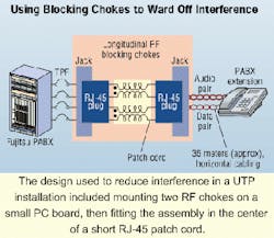
When it was implemented in the field, the solution reduced the interference to a barely perceptible and quite satisfactory level. Physically, the implementation of the design consisted of mounting two chokes (one for each pair in use by the handset) on a small PC board and fitting the assembly with some protective heatshrink-all mounted in the center of a short RJ-45 patch cord.
This solution is neat and low-cost, and permits easy installation without the need for hard wiring. Problem solved!
George Georgevits manages Power and Digital Instruments Pty. Ltd. (PDI), Australia, which specializes in lab- and field-testing of cabling systems and components, electronics design, and troubleshooting. This article is reprinted from August/September 2000 issue of our sister publication, Cabling Installation & Maintenance Australia-New Zealand.

