What you can do about preventable fiber-link failures

Maintenance procedures give new meaning to the term "clean data."
One of the primary questions on the minds of end-user organizations, or anyone who pays for network downtime, is why fibers fail. Wherever fiber links are used in a network-and very few networks don't have at least some fiber-the optical-fiber cabling becomes critical to overall network performance. So, maintaining top-quality cabling becomes essential to network owners.
To help understand the causes of network failures, Fluke Networks (www.flukenetworks.com) commissioned an independent study of private-network owners and installation contractors. The study was conducted by Martin Technical Research, and was intended to determine the most common causes of fiber failures. The results of the study revealed that fiber inspection and certification tools not only identify the problems, but in many cases they fix them as well.
Installing optical-fiber links
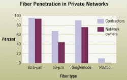
Installation of a well-performing network using fiber links requires placing cable, terminating connectors on each end of the cable, and making connections (via patch cords) to equipment at each end. When placing cable, it is important not to incur harsh bends along the way, which can cause excessive attenuation in the link. Those that responded to the study are primarily installing 62.5/125-micron (µm) fiber cable, while there is also a strong showing for 50/125-µm cable. In addition, the ST and SC connectors are still the primary connectors of choice.
Terminations have a significant effect on link attenuation, and they can also cause modal disturbances in multimode systems. Connectors are installed either by splicing to a prepolished stub that is found within the connector, or by field polishing. When prepolished connectors are used, you generally don't feel the importance of viewing the connector's endface, since the end is manufacturer-polished in a controlled environment.
For installing field-polished connectors, you typically inspect the endface with a magnifying glass or a 100x microscope. When you're confident that the termination is good, you place the connector into a panel or outlet, waiting to be tested for attenuation readings. Here, labeling is critical because you must ensure that the transmit side of the fiber on one end is labeled for receive at the other end.
The recent research uncovered that you're doing a great job with the tools you have. The study showed that 86% of installation contractors are using a microscope during this important phase of the job, while 80% of network owners use microscopes for fiber inspection. The challenge, then, was determining the reasons for the high percentage of fiber-failure rates when good installation and maintenance practices are so common.
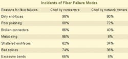
Eighty-nine out of the 100 installers and network owners surveyed cited dirty connector endfaces as the number-one problem encountered during fiber installation.
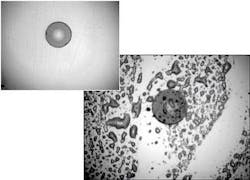
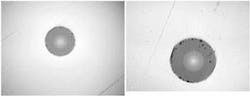
While it is common to use a 100x magnification device to look at connector endfaces, these low-powered scopes will not always show particles of dirt or scratches on the connector endface. Often, when 100x magnification shows little dirt, higher-magnification scopes reveal dirt in the fiber core where the signal is going to travel. In general, 250x scopes are ideal for multimode installations, while the power of a 450x magnification is recommended for singlemode applications.
•Author tip: When using a microscope to view fiber endfaces, make sure you use one with laser-safety filters to prevent infrared light in live fibers from reaching the user's eye.Problems found while troubleshooting
Troubleshooting fiber-link problems is the last step in the installation process. Many times, troubleshooting occurs when the installed link does not pass the loss test specified in the work contract. Some users also troubleshoot during electronic-equipment installation. Oddly enough, fiber endface inspection is not always carried out during this phase of ensuring system performance.
One of the primary reasons for not inspecting the endface is that access to terminated fibers in a patch panel or outlet is not conducive to maintaining fiber-cable management. The process can be quite time-consuming. Although times vary, it generally takes about 10 minutes to uncouple the fiber from the adapter at the rear of the patch panel, route the connector through the fiber-management system, view the endface, reroute the cable, and recouple the connector to the adapter. And when you've carried out this process, hopefully, you haven't accidentally touched the end of the connector, placing even more debris on the endface.
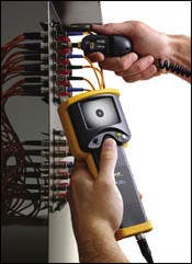
A cost-effective way to inspect these fiber ends is to use a video microscope. It provides the reach to get into the patch panel, as well as into equipment ports of electronics, thereby sharply reducing the time required to inspect a fiber end. Video microscopes are available with magnification up to 400x, with a variety of connector types, including small-form-factor. They also are safe, eliminating any chance of damaging your eye with harmful infrared light.
Viewing endfaces with a video microscope can be accomplished in one minute-one-tenth of the time required for using a traditional microscope. That means you can view six connectors in six minutes with a video microscope, compared to one hour with a traditional microscope. If you are inspecting both ends of a 48-fiber cable, the time saved by using a video microscope would exceed 14 hours.
Installers and system owners alike can use video microscopes on active electronics, because the scopes are safe from infrared light. For example, if a port on a 100Base-FX 24-port switch is not working, you could look for dirt on the port using a video microscope, even if the equipment is turned on and all other ports are active. This way, you may be able to identify the trouble and work with the electronics-manufacturer to rectify the problem.
•Author tip: Visual inspection of your electronic-equipment ports may reveal that the trouble is really dirt. Before cleaning the port, contact the electronics manufacturer to ensure that you are not voiding your warranty.An interesting fact about installing a dirty fiber connector-it gets the mating connector dirty. That's one reason why cleaning the endface of a test-lead cable is so important. If you test with a dirty test cord, you not only have higher loss readings, but also contaminate the fiber endfaces you are checking. Conversely, remember that your test cord can pick up dirt from a dirty connector. Also, think about how many patch cords you typically install without inspecting the ends or cleaning them appropriately. Accidentally touching an endface can lodge significant amounts of dirt onto it. These cords have been found to be a source of many network troubles. Quite frequently, the installer or network owner connects a system to devices and unknowingly has missed inspecting more than half of the potential problems: connections on the patch cords and equipment cords.
Interestingly, 90% of contractors surveyed inspect the fiber endface every time they install a connector, as do 80% of network owners. Their comments stated, in general, that they use 100x-power microscopes. A few use 200x scopes. When cleaning the endfaces and bulkhead adapters, contractors use alcohol 92% of the time, and network owners use it 82% of the time. Contractors use compressed air on 30% of their endface cleanings, and network owners use it 12% of the time. Some combine both methods. Others clean connectors with a well-soaked alcohol pad, and dry them with a lint-free cloth because they believe that using compressed air or alcohol alone can leave residue on the endface.
Dirty, broken, and poorly polished endfaces are the primary enemy of data transmission over optical fiber, especially that of high-speed networks. Application standards like Gigabit Ether net are calling for link budgets of less than 2.4 dB.
In systems with such tight loss tolerances, dirt can have an overwhelming effect. Fortunately, many solutions can help installers and network owners easily identify dirty connections. There is no excuse for not being able to ensure that clean fibers will provide great data streams.
Top 10 ways to ensure clean fiber connections
null
By simply inspecting connectors for cleanliness and using dustcaps, you can eliminate common problems caused by dirt and other contaminants. But when you do run into trouble, the proper tools and practices can greatly reduce downtime and its overall cost. Here are 10 procedures to think about:
- Pull fiber cable by its strength members, and do not violate cable bend-radius specifications.
- Clean connectors during the installation phase according to manufacturer recommendations.
- Verify cleanliness of fiber connectors and check for scratches using a high-power video microscope with at least 200x magnification power.
- Verify polarity of the fibers using a visual fault locator or dual-source optical-loss test set.
- Test cabling installations with an optical-loss test set and an optical time-domain reflectometer per construction specifications.
- Use clean test cords when testing cabling links ... and keep them clean.
- Use a video microscope to check fiber ports for all active networking equipment.
- Use a video microscope to check the ends of patch cords.
- Install dust caps on all connectors.
- When trouble arises, don't second-guess by swapping patch cords and ports. Save time and money by using fiber-inspection and troubleshooting tools to accurately identify and eliminate the root of the failure.

