Revised BICSI manual sets pace for hands-on cabling installation
Forthcoming third edition adds detail to wide-ranging techniques and issues.
In its "By the Book..." column, Cabling Installation & Maintenance has provided brief reviews of many of the cabling manuals and handbooks that have been published in recent years. Nowhere, however, is there a more detailed, comprehensive, and authoritative guide to this rapidly evolving area than in the Telecommunications Cabling Installation Manual (TCIM) published by BICSI (Tampa, FL).
In this special report, we will take an in-depth look at the forthcoming third edition of TCIM. Along the way, we'll explore some areas of installation practice that are a bit off the beaten path.
BICSI is an international professional association focusing on telecommunications infrastructure issues. Until recently, its focus has been on infrastructure design, a subject covered in great detail in its two- volume Telecommunications Distribution Methods Manual (TDMM), now in its ninth edition. The TDMM has served as the basic training document for what has come to be the essential credential for telecommunications infrastructure designers-the Registered Communications Distribution Designer (RCDD) designation. BICSI awards the RCDD to those who can demonstrate substantial design experience and who can pass a stringent examination based on the contents of the TDMM.
A broader focus
In 1996, the organization's board of directors decided to broaden its scope to cover telecommunications infrastructure installation as well as design. A separate training program for cabling installers was set up, including classroom and on-the-job training curricula, instructional workbooks, and an examination and registration program. The initiative was launched at the first annual Cabling Installation Expo, held in Charlotte, NC in the fall of that year and presented in conjunction with Cabling Installation & Maintenance magazine. BICSI organized a series of training workshops for the event, while its partner, PennWell's Communications & Opto-Electronics Group (Nashua, NH), managed the exhibitions.
Today, BICSI's installer training program has trained more than 10,000 installers, and has grown much more rapidly than the organization anticipated at first. BICSI master instructors teach seminars throughout the year and all over the world. But the not-for-profit organization is careful to license other training groups, both for-profit and nonprofit, to present its curriculum. BICSI is also committed to making its training program generic, so that it does not favor individual manufacturers and their product lines, and it encourages vendors to offer its training in lieu of their own product-specific certification programs.
Formally dubbed the BICSI Telecommunications Cabling Installation Training and Registration Program, installer training is conducted at three levels. The lowest level, designated Apprentice level in the past, has recently been renamed Installer Level 1 to prevent confusion with electrical apprenticeship training programs. Each level-Installer Level 1, Installer Level 2, and Technician-requires classroom and on-the-job training, as well as work experience in the field, and leads to registration upon passing an examination. Classroom training is based on workbooks derived from the Telecommunications Cabling Installation Manual.
The TCIM, like all BICSI manuals, is primarily a volunteer effort, with a committee submitting information and reviewing the drafts while the BICSI staff is responsible for the actual assembly and editing. Along with its designer and installer registration programs, BICSI offers specializations in local-area networking and customer-owned outside plant, each of which is supported by a comprehensive manual. A residential-cabling specialization is also in the offing, and will debut in the fall.
The Telecommunications Cabling Installation Manual is published in a large looseleaf binder. It is also available on CD-ROM, and BICSI has arranged with technical publisher McGraw-Hill (New York, NY) to sell the manual in bookstores and online as well.
An extensive opening chapter of the TCIM covers many of the basics that cabling installers need to know about. Subsections of the chapter deal with:
- A brief history of the telecommunications industry, covering the convergence of voice and data technologies and locating both the cabling-installation marketplace and BICSI within this wider framework.
- An overview of structured cabling, describing the various components of a structured cabling system (SCS), from entrance facility to work area, and explaining why a generic, standardized approach to cabling is the best policy. The section concludes with explanations of various cabling topologies.
- Codes and standards, with emphases on the National Electrical Code and the five core infrastructure standards of the Telecommunications Industry Association (TIA-Arlington, VA).
- Planning documents and specifications, including architectural drawings and construction specification.
- The primary commercial-project cabling media: twisted-pair, coaxial, and fiber-optic cables.
- Connectorization of the cabling media types.
- The principles and terminology of signal transmission over both copper wires and optical fiber.
- Grounding and bonding concepts and procedures.
- Common safety practices, including electrical safety and procedures for working in enclosed spaces.
- Professional considerations, such as customer relations.
Subsequent chapters focus on:
- The construction and installation planning process, from responding to an on-site survey to issuing a change order.
- Installing supporting structures, such as racks, cabinets, trays, and conduit.
- Cable-pulling procedures and techniques, beginning with planning the pull and covering both horizontal and backbone cabling pulls in horizontal and vertical environments.
- Firestopping, including an explanation of the basics, identifying the many different types of firestops, and showing step-by-step how they should be installed.
- Termination practices used for all major cabling media at connecting blocks, patch panels, and work-area outlets.
- Splicing of both copper cable and optical fiber.
- Test equipment and test procedures for twisted-pair, coaxial, and optical fiber cable in both horizontal and backbone applications.
- Troubleshooting equipment and methods.
- Planning and executing retrofit installations, with an emphasis on their differences from new construction.
As noted, the third edition of the TCIM is due out in late June. The cabling industry has been changing rapidly over the last few years, and it is clear from a review of the revisions that the third edition will differ substantially from the second. Among the major changes will be:
- Discussion of the Telecommunications Reform Act of 1996 and its effect on deregulation of the telecommunications industry.
- Updated to reflect the latest ANSI/TIA/EIA standards.
- Additional coverage of Canadian and international codes and standards.
- Addition of Category 5E UTP and ribbon fiber-optic cables.
- Coverage of safety planning in addition to existing coverage of safety practices.
- A major expansion of the sections on construction planning and documentation.
- Extensive revision of and addition to the chapter on cable pulling.
- A completely rewritten chapter on firestopping.
To provide a better feel for what will be found in the third edition, BICSI has agreed to let Cabling Installation & Maintenance excerpt several sections from the manual. The sections selected have been chosen with an eye to covering some installation issues that rarely get dealt with otherwise. Keep in mind that the manual is still being edited, and that the words and illustrations you find on the following pages may not be exactly the same as what appears in the published manual.
To purchase the new edition, contact BICSI at 1-800-242-7405 or (813) 979-1991, or order online at www.bicsi.org.
Arlyn S. Powell, Jr. is Editor-At-Large and Associate Publisher of Cabling Installation & Maintenance.
Topologies determine how the network will perform
An item's topology refers to its features, shape, or physical appearance. For example, a topological map represents the physical appearance of the area shown. Cabling topologies can have physical, electrical, or logical configurations. In many ways, a standard cabling plan's topology is both physical and logical-it is representative of both the plan's features and its physical appearance.
Local area network (LAN) topology is related to the topology of the physical media that supports it. LAN topology is primarily determined by how transmission channels are used to connect network devices. Typically, the term refers to how the LAN is physically set up, its electrical and logical configuration, and the cabling strategy being used. It is acknowledged that topology is the foundation of a LAN.
Within the context of LANs, the word topology takes on a dual meaning. Both aspects are important to how the LAN will function:
- First, topology refers to the physical appearance of the LAN. This is known as the physical topology.
- Second, topology refers to how the LAN functions. This logical topology is determined by how the messages are transmitted from device to device.
There are many instances where a LAN has a certain physical appearance but logically transmits its messages in a different topology. For this reason, it is necessary to make the distinction between the physical topology and the logical topology of a LAN.
The purpose of this article is to illustrate the physical appearance of a number of LAN topologies.
There are three fundamental topologies-star, bus, and ring. From these three, a number of hybrid topologies have developed, including tree, star-wired ring, clustered star, and hierarchical star.
In structured cabling systems, the required physical topology is the star topology. Because it can be configured to accommodate each of the logical topologies-star, bus, ring, and hybrids-the star topology offers the greatest flexibility.
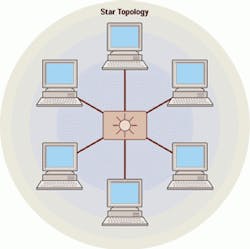
Star topology
In a star topology, the hub or switch is placed in the physical, as well as logical, center of the network. The remaining network devices are connected to this central hub like the points on a star.
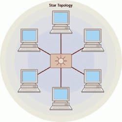
Each device has its own direct, dedicated line to the hub or switch. Any network device wanting to send a message to another network device does so through the central hub. The station sending the message sends it to the hub. The hub then routes the message to the specified destination station-this is known as switching.
A star topology has these advantages:
- Cabling is easier to install and maintain.
- If one device is disabled or isolated from the central hub, it is the only device affected.
- Faults are easier to locate and isolate.
- It provides a central location for managing the network.
The star topology has this disadvantage:
- It may be vulnerable to breakdown, since the network is essentially controlled by one device at a central location.
Bus topology
A bus topology is a linear configuration. It places all of the network devices on one length of cable, located similarly to stops on a city bus route. The hubs, server, stations, and peripheral devices all use the same continuous length of cabling.
The ends of the cable in this arrangement are not connected to network devices. Ordinarily, problems would occur when the transmitted signal is sent along the cable and it reaches either of the ends. For this reason, each end of the cable is connected to a terminator.

When a message is sent utilizing this topology, the transmission signal leaves the sending device and travels along the cable in both directions. The device for which the message is intended will recognize the transmission and read the message.
Bus topology has these advantages:
- It is easily adaptable to many environments-it can be configured to suit most situations.
- It is easily expandable by adding devices at various points along the cable.
Bus topology also has disadvantages:
- It lacks central control-finding a fault is difficult.
- If the cable is damaged or if either end of the cable loses its termination, the entire network will fail.
Ring topology
A ring topology places all of the network devices in a circle. It uses one cable to connect all devices. Each device is connected to the next one, and the last device is connected to the first, closing the circle.
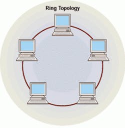
When a message is sent, it travels from device to device around the circle. The sending device sends its message towards the destination device, and each device between the sender and the receiver listens to the message as it passes by. If the message is not intended for a particular device, it resends the message, and the next one in the ring repeats the procedure. This continues until the intended destination receives the message.
Although the ring topology is considered as one of the three fundamental network topologies, it has never been popular in its basic form. The more popular dual-ring topology provides two paths between stations-a primary path and a backup path. In the event of a failure in the primary path, the signal can be diverted to the backup path by stations on either side of the point of failure, preventing total network failure.
Ring topology has one major advantage:
- There is no reliance on a central device-all messages pass through all devices.
Ring topology, however, also has disadvantages:
- Additional network devices can only be connected while the network is inoperative, since breaking the ring would cause network failure.
- If any device fails, the entire network is affected.
Hybrid topologies
Hybrid topologies result from a need to meet specific requirements or industry technological advancements. While there are many variations on the three topologies discussed earlier, certain hybrids are more popular than others.
Tree topology
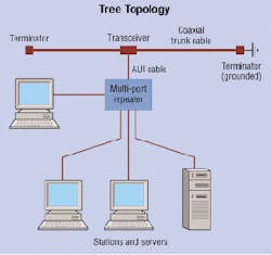
The tree topology is an extension of the bus topology. By adding cable extensions to the basic bus topology, a larger network can be achieved using less cable. Each additional cable extends from the underlying bus structure and supports multiple network devices along its length.
Star-wired ring topology
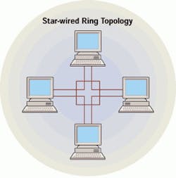
A star-wired ring is also referred to as a collapsed ring. In this configuration, the network devices are connected to each other as they are in a ring topology. The difference is that they are connected through a central unit, which acts as a wire center. The transmission method is the same as with the ring topology, except now dual rings are present-one primary and the other backup. All messages must first pass through the wire center before moving to the next device. The main improvement over the ring topology is that the failure of a single device will no longer cause the whole network to fail, due to active monitoring by the wire center.
Clustered star topology
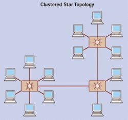
A clustered star is much like the tree topology, except that there are clusters of devices at the end of each branch. An underlying bus configuration supports cable extensions. Each of these cable extensions has a cluster of network devices at its end. This is also known as a bus star configuration.
Hierarchical star topology

A hierarchical star topology is an extension of the star topology. In this configuration, departmental network devices are connected to a hub or switch as is the case in a star topology. These hubs or switches are then connected to each other via a central hub, also following a star configuration. This is the recommended topology for structured-cabling backbone systems in buildings and in campus environments.
Confined spaces call for special safety procedures
According to OSHA regulation 1910.146: Permit-Required Confined Spaces, "a confined space:
- Is large enough and so configured that an employee can bodily enter and perform assigned work; and
- Has limited or restrictive means for entry or exit (for example, tanks, vessels, silos, storage bins, hoppers, vaults, and pits are spaces that may have limited means of entry); and
- Is not designed for continuous employee occupancy."
Maintenance holes, splice pits, crawl spaces, and attics can fall under this definition of a confined space provided by the Occupational Safety and Health Administration (OSHA-Washington, DC).
Confined spaces may require testing for a hazardous atmosphere because they may contain:
When toxins, gases, or combustibles are detected, the cabling installer shall:
- Provide continuous forced-air ventilation to purge the contaminants from the space.
- Periodically monitor the air quality within the space.
- Evacuate the space immediately if contaminants return.
- Determine why the contaminants returned and take corrective action prior to re-entering the space.
Certain confined spaces may require:
- Breathing apparatus.
- Protective clothing.
- A trained safety person stationed outside the space.
- A lifeline attached to the worker inside the space.
Hazards from toxic or flammable gas are rare when working inside a building. Telecommunications rooms and equipment rooms should, therefore, be completely free of gas hazards. However, there may be some situations where a sealed vault-type structure-for example, an entry facility or splice pit-may accumulate gases.

Always use caution when entering any room or work area that is marked with warning signs that prohibit open flames or indicate other potential gas hazards.
When opening a vault-type structure, treat the vault like a maintenance hole. Before entering the vault, use a gas detector to determine whether any dangerous gases are present. If dangerous gases are present, the gases must be cleared from the vault before any worker enters it.
Testing a maintenance hole for gases and exhausting gases out of it are usually outside-plant procedures and are outside the scope of this article. Detailed descriptions of these procedures are available in OSHA 1910.146, and 1910.146, Appendixes A-D.
Installing backboards in the telecommunications room
It is recommended that telecommunications rooms (TRs) have 20mm-(0.75-in)-thick plywood backboards installed on at least two walls of the TR. The plywood provides a structure on which to mount connecting hardware and secure cables and equipment. A 300-mm (12-in) wide cable tray or ladder rack should be mounted on the same wall or walls as the backboards. If possible, in fact, mount plywood and cable tray or ladder rack on all walls of a telecommunications space to facilitate growth.
The telecommunications designer's documents should indicate the size, location, quantity, and nomenclature of the equipment to be installed in the room, along with a routing diagram of the cables to be installed or that pass through the room. These drawings will also show the location of the pathways entering or leaving the space, but may not necessarily note who is responsible for installing them. If equipment racks are to be installed, a plan view of the space will indicate their footprints and will show how they relate to other equipment being installed. In most instances, the telecommunications designer's documents will indicate where voice, data, and video cables are to be terminated.
Always ensure that appropriate clearances are maintained around all pieces of equipment. In the absence of a specified distance, plan for a minimum of 1 m (3.3 ft) of work and aisle space between and around equipment. If a TR layout is not provided, prepare one for approval before starting work. Details for laying out a telecommunications room may be found in the most current edition of the BICSI Telecommunications Distribution Methods Manual (TDMM) and can be referenced before beginning the work.
Some of the major points to remember when complementing the design of a TR include:
- Space for all planned and future equipment.
- Adequate routing pathways for each type of cable.
- Proper support for each type of cable, including growth.
- Adequate working room, including any needed clearances from equipment.
- Sufficient lighting, electrical, and other environmental support.
- Physical security.
- Distribution pathway access for both horizontal and backbone cables.
- Product manufacturer's recommended installation practices.
It is important that the cabling installer prepare at least a dimensioned sketch of the space and equipment to be installed in order to identify potential areas of conflict. The simple concept of "build left to right" may not apply when faced with cable terminals, equipment racks, overhead lights, network equipment, and patch panels. Design field adjustments may be necessary.
Plywood backboards
Plywood backboards are employed on walls in telecommunications rooms. Plywood is available in two types-interior and exterior-and in four grades-A, B, C, and D.
Sheets of plywood are normally sized 1.2m (4-ft) wide by 2.4m(8-ft) high. The thickness is variable, but, for the purposes of this article only two will be considered: 20mm (0.75 in) and 25mm (1 in). Plywood that is too thin allows the screws used by cabling installers to penetrate completely through the plywood and sometimes does not offer enough strength to ensure that mounted hardware is securely anchored. Plywood sheets thicker than 25mm (1 in) are not usually required. This, of course, is contingent on the sheet of plywood being properly attached to the building structure.
The finishing grade of plywood-A, B, C, or D-describes the quality of the surface, including the number of knotholes or blemishes.
- Grade A is the highest grade and is without any surface blemishes.
- Grade B has the knotholes cut out and replaced with a patch of clean wood.
- Grade C contains some blemishes and an occasional small knothole.
- Grade D contains knotholes without any repair or corrective action by the manufacturer. Grading of a sheet of plywood may result in a different grade for each of the two sides. For instance, a sheet of plywood could be graded A/B-one side is A, and the reverse side is B.
Plywood should also be void-free. This means that the space in each layer inside the plywood where the knotholes are removed is completely filled with replacement wood patches. Voids inside the sheet of plywood may create a weak spot where the attachment hardware-screws or toggle bolts, for instance-may not be able to hold fast.

For telecommunications use, grade A/C should be used. The A side is exposed to the interior of the TR and the C side placed against the building structure or cabinet wall. Generally, start mounting the plywood 6 in above the finished floor (AFF).
The effects of the treatment will cause the paint to crack, deteriorate, and peal off the plywood backboard. In addition, the saline solution can cause the metal hardware mounted to the plywood to corrode. (Note: Some local codes may require the use of treated plywood. If this applies, do not paint the plywood.)
Placement of backboards
Plywood sheets used for backboards should be installed with the longest dimension reaching from the floor level up toward the ceiling to its 2.4m (8-ft) height. In the case of a 2.7m (9-ft) or 3m (10-ft) ceiling, do not succumb to the temptation to raise the bottom of the plywood to split the difference. This will raise the working height level such that a ladder may be required to work on equipment mounted at the top of the plywood.
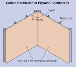
Plywood should be installed in such a manner that there is no separation between adjacent sheets. When installing plywood in a corner, the plywood backboard can be installed plumb and adjacent to the edge of one side of the wall at the corner, with the sheet on the intersecting wall butted up against the first sheet to form a smooth, 90° corner.
The plywood backboard must be secured on top of the existing drywall or to the studs in the perimeter walls of the room. When installing the plywood on bare studs without drywall, drywall screws a minimum of 13mm (0.5 in) longer than the depth of the plywood backboard must be used.
When installing plywood on drywall that has already been installed on the studs, always verify the load rating of the wall prior to installing the plywood. If the load rating will permit this type of installation, use toggle bolts (butterfly bolts) to ensure the stability of the installation. These toggle bolts should be a minimum of 6mm (0.25 in) in diameter and must be sufficient in length to allow the bolt to seat behind the drywall after installation.
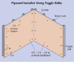
For this drywall application, toggle bolts should be installed at approximately 609mm (24 in) spacing around the entire perimeter of the plywood board. If desired, recess the bolt heads to allow for use of the entire area on the plywood. Never recess the bolt head on any plywood less than 25mm (1 in) in thickness. This will affect the ability of the plywood to hold the desired load of equipment and termination hardware. The toggle bolts should be installed 50mm (2 in) from the edges of the sheet of plywood on approximately 609-mm (24-in) centers. Locate the toggle bolts using care to avoid the studs when drilling. The studs will prevent the toggle bolt's wings from opening behind the drywall.
Layout of backboards
If possible, install plywood backboards around the entire perimeter of the TR. This will enhance the use of the wall space in the TR and allow cables to be installed around the walls to where terminal equipment will be located, now or in the future. It will also facilitate attaching cables that pass through vertically to TRs above or below.
A typical telecommunications room might include some or all of the following:
- Twisted-pair modular IDC cross-connect field for horizontal and backbone cables.
- Modular patch panel for twisted-pair horizontal cables.
- Optical fiber backbone cable terminal.
- Optical fiber horizontal cable terminal.
- Equipment racks.
- Cable tray or ladder racks.
- Telecommunications ground.
- Active and passive network equipment-voice, data, and video.
- Other low-voltage systems.
- Environmental support systems, including lighting, electrical services, and air-handling services.
- Firestopping system.
- Room for expansion.
- Sleeves (floor and wall).
System cutover: nail-biting time for any installation
With the system acceptance testing complete, the installation team is ready to put the new system into service, a process known as system cutover.
The cutover is handled differently for every installation. Some are as simple as installing a new system, turning it on, and using it. Other retrofit systems are installed next to old systems but are completely separate, so that both can operate at the same time until the final cutover.
Situations where the new system can be installed while the old system is left in service are the safest way to handle the cutover. The new system is installed, tested, and then put into service. The users are asked to start using the new equipment. The old system remains in operation as a backup. Any users who experience problems can go back onto the old system until the new system can be corrected or the users can be properly trained in the use of the new system.
The old system can be disconnected and removed after the users are comfortable with the new system and the system has had a chance to burn-in. The term burn-in refers to the electronic circuits getting warm when they are turned on. A new system should have a low percentage of its circuit boards fail after they have been initially turned on and allowed to heat up.
Each job may require different amounts of burn-in time. It can range from a week to six months. It may be phrased as: "The new system shall be considered accepted after a 45-day burn-in and 31 days without a failure." This protects the customer from getting a new system that is losing a circuit board every other day. There have been systems installed that have not been accepted for over a year due to continuous equipment failures.
Ask the customer the best time for cutover and how long the system can be out of service. Check for any circuits that must remain operational throughout the entire project.
Documentation and installation manuals for all the equipment being installed must be on site during the cutover. Also, a set of manuals for the equipment being removed should be on site. They can be useful if it is necessary to return to the old system.
There are several phone numbers that can be helpful if complications occur during a cutover. The numbers should be researched in advance so time is not wasted when the customer is without communications. Some of these phone numbers include:
- Internet access to download files from the manufacturer.
- Manufacturer's technical assistance.
- Local central office.
- Long-distance providers.
- Special circuits providers, such as for T-1s, optical fiber, and wide area network (WAN).
Make a list of every circuit number entering the facility, so they may be given to service providers to provide assistance.
Most installers think of a cutover taking place on the weekend or in the middle of the night. These may not be the best times for the customer or the local service providers. For example, the customer may download files from around the world between the hours of midnight and 4 A.M. each morning. Technical assistance from the service providers after hours may also be a problem. Most service providers use a reduced staff after normal working hours.
If a problem is experienced with the new system, it may also be difficult to get technical assistance from the manufacturer after hours. Contact the manufacturer ahead of time and ask about its after-hour assistance policy. If required, establishing an account with the vendor for technical assistance may be beneficial. Note that many manufacturers now charge for technical assistance. Most also require a technician's certification number prior to giving assistance.
Performing a cutover on the weekend requires a great deal of coordination. Notify the users of the pending cutover, and provide initial training on how to use the new system.
When installing a private branch exchange (PBX), the cabling installer should:
- Deactivate and remove the existing system.
- Install the new system.
- Cross-connect the backbone and horizontal cables to the new system.
- Transfer the entrance trunks and tie lines to the new system.
- Install, test, and label new user instruments.
- Perform acceptance testing on the whole system.
When installing a new data network, the cabling installer should:
- Install the new cabling system.
- Install and configure the new system electronics.
- Install and configure the new network interface card (NIC) and existing NIC card in each terminal.
- Cross-connect the backbone and horizontal cables to the new system.
- Test each terminal's ability to log onto the network.
- Install, test and label peripheral devices, such as printers and modems.
- Transfer any entrance tie lines to the new system.
- Perform acceptance testing on the whole system.
- Deactivate and remove the existing system.
The new system should be ready for the users when they arrive at work. No matter how thoroughly the system is tested and put through its paces, though, be prepared for problems. When the users start full-scale loading, trouble reports will be received.
A crew should be on site and a notice placed on every user's telephone, explaining how to use the system and listing one telephone number to report troubles. The users should be informed that the cabling installers are on site ready to fix troubles and provide training. This should encourage users to report troubles and ask questions right away.
Steps in cutover
null
Step 1
Cutover
Method of implementation
- Confirm whether work will be performed after or during normal business hours.
- Identify cables to be removed prior to the completion of the project.
- Remove all cables and cross-connects that are not supporting active circuits and are scheduled for removal.
- Develop cutover sheets.
- Install temporary cabling, if required.
- Float backboards, racks, and equipment, as required.
- Install new cabling.
- Install and configure new equipment.
- Confirm the cutover time with the customer.
- Notify the users of the cutover and provide training on the new system.
- Verify who is responsible for the interconnection of voice and
Step 2
Cutover
Testing- Perform copper testing of all new cables for either link or channel tests, as determined by the customer.
- Perform fiber testing, using either an optical power meter or OTDR, as determined by the customer.
Step 3
Cutover
Documentation- Label all equipment, pathways, and cabling as appropriate.
- Update blueprints for "as-built" documentation.
- Provide updated cross-connect records.
- Provide interconnection drawings.
- Provide rack layout drawings.
- Compile all test results in both hard-copy and electronic media for the customer and the installation company's records.

