Underfloor cabling strategies rise to the challenge
A telecommunications service company applies a zone-cabling solution within a raised-floor system.
Infonet is a global telecommunications service company that provides wide-area telecommunications network services in approximately 180 countries around the world. Infonet's new global corporate headquarters building in Segunda, CA-the construction of which was completed approximately a year ago-is a three-story structure encompassing 150,000 square feet of office space. The 500-plus employees located in Segundo are involved in engineering, finance, sales, and information technology (IT). The company's global network management center-a help desk operation and global network fault monitoring-is also housed in this facility.
According to Tim Hoffmann, Infonet's infrastructure architect, the computing environment is what one might expect in a corporate headquarters. Lotus Notes and Microsoft Office are the commonly used applications; Novell NetWare provides file and print services for the network; the database is from Oracle; and Sun Solaris-based computers are used for some customer-relationship-management applications.
Before construction began on the new building, Infonet had been operating in leased space nearby. When the decision was made to build a new headquarters, the main priorities focused on workspace flexibility and a long, useable lifetime for the structure.
The old headquarters had conventional hard-walled offices, but the new structure, in line with the desire for flexibility and adaptability, is almost completely open-plan in layout. Other than four hard-walled offices and several conference rooms, all three floors are devoted to modular offices and cubicles.
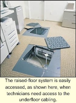
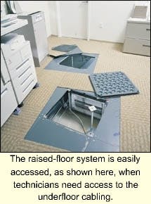
To further support a flexible arrangement plan, the building was designed to use raised flooring throughout. The raised floor, suspended 18 inches above the concrete slab subfloor, lets all services run underfloor-including electrical and communications cabling; plumbing; and heating, ventilation, and air conditioning (HVAC).
Flexibility by design
For communications cabling, raised flooring has obvious advantages, which is why it is practically a must for computing centers. Infonet chose to capitalize on raised flooring's advantages and extend them throughout the building. The raised flooring also had won the architect's recommendation, based on increased cooling efficiencies compared to an overhead plenum.
Instead of running ducts under the floor, the construction crew created air highways to channel the airflow to proper locations. The concrete slab subfloor served as the bottom of the air highway, while the undersides of the raised-flooring panels formed the top. HVAC contractors built sheet-metal "fences" that extended from the subfloor to the raised floor to form the sides of the air highways.
Infonet issued a request for quotation for the communications cabling, and received about a half dozen bids. After analyzing the bids, Infonet awarded the job to Vector Resources Inc. (Torrance, CA). Vector based its bid on AMP Netconnect cabling systems from Tyco Electronics. The AMP Netconnect system supports both the structured wiring concept commonly used today, as well as the zone concept (see sidebar, "The zone approach," pg. 32). The zone system uses consolidation points as intermediate concentration points between the telecommunications rooms (TRs) and the user work areas. Vector Resources had recommended a zone cabling design as the best complement to a raised floor. Indeed, Infonet's Hoffmann considers zone cabling "the only thing that makes sense for raised flooring."
While running the communications cabling under the floor has some advantages, it also presents design and installation challenges. According to Ryan Stachowiak, the sales representative at Vector responsible for the Infonet account, with every system-including electrical, HVAC, plumbing, communications, and fire suppression-running underfloor, "it took a lot of coordinating between all of the trades. Everyone had to work together to make this thing a success."
Bob Schuman, RCDD, Vector's project manager and chief cabling designer for the Infonet job, and architect Nelson Algaze of the firm Shlemmer, Kamus & Algaze were also actively involved in the coordination.
This type of team collaboration was necessary in both the design and installation phases. The design phase required establishing which portions of the underfloor area would be dedicated to the air highway and to each of the other services. Changes in the routing of electrical wiring, for example, could easily impact the communications-cabling layout.
According to Schuman, "There was at least one TR built atop an air highway, so we had some restrictions with one of the IC [intermediate crossconnect] closets. We also had a lot of pass-throughs, where cabling had to cross sections of the air highway." As a result, customized sheet-metal viaducts, running crosswise under the air highway, were created. All cabling that crossed the air highway was run through these viaducts, and everything was fire-sealed and made airtight.
The installation phase also required detailed advance planning and scheduling, to determine what systems would be laid down in what order.
Challenges met
The design phase required the planners to think, literally, on three different levels:
- The underfloor layer (including cable routing and the location of consolidation points);
- The raised floor (including, most critically, the precise location of the floor boxes that hold the faceplates and jacks); and
- The layer above the floor (including the modular furniture and walls).
Any changes in the furniture layout would directly impact the placement of floor boxes that support each user.
Hoffmann notes that the architect was able to supply computer-aided design (CAD) drawings for the building. The firm that supplied the modular office systems used these drawings as the basis for developing a layout for the modular offices. Vector Resources merged the two sets of CAD drawings, developing a CAD layout for the cabling infrastructure.
An issue that designers must consider is that any errors in the layout process for the modular furniture can cumulatively add up to significant overall errors when a dozen or more offices are laid out in a row. A great deal of care is necessary to ascertain, for instance, whether measurements will be taken from the centerline of one modular partition to the next. If this is not carefully assessed, then a cabling floor box can easily end up directly under a user's chair instead of neatly tucked away near a partition.
To keep things relatively simple, none of the cabling goes into the modular partitions or the modular furniture. Receptacles for electrical power, voice lines, and data lines are mounted in a floor box that is known as a PVD box-for the power, voice, and data circuits that it carries. The PVD, in turn, is fitted into a cutout in the raised floor panel. In Infonet's cabling scheme, each PVD is furnished with two electrical circuits (one low-capacity and one high-capacity), three data drops, and two voice drops. The communications jacks are connected to the underfloor CPs. One PVD is used for each user work area, and one or two per conference room.
The cabling that connects the AMP Netconnect CP to each user location is available from Tyco Electronics as a completed cable assembly. For these assemblies, the cabling is cut to the specified length, terminated with the appropriate connectors, and tested. Once the CPs have been placed and cabled to the TR, all an installer needs to do to put in a new cabling drop is plug one end of the pre-made cable assembly into the CP and, at the user end, snap the pre-mounted 8-pin modular jack into the PVD faceplate.
Cabling plan
The building is shaped in a "T" configuration, with three wings. A TR is located at the end of each leg on every floor, except the ground floor, where the main computer room also serves as a TR.
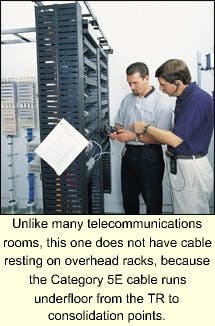
In broad outline, the cabling plan was to use AMP's Category 5E unshielded twisted-pair (UTP) copper cabling in the horizontal system. Category 5E CPs from AMP would be located in appropriate positions at various points under the raised flooring, and Category 5E cabling would run from the TRs under the floor, out to the CPs. Pre-made transition cable assemblies would be used from the CPs to the individual user locations.
Three Category 5E cables were run to each PVD for the three data drops. For voice, a single four-pair Category 3 cable was used to connect both jacks on the PVD box. Two pairs were connected to the primary voice jack, and the other two pairs were used for the secondary voice jack.
In the TRs, Infonet uses Nortel BayStack network switches, providing users with 10/100-Mbit/sec switched Ethernet to the desktop. AMP Netconnect 24-strand multimode fiber connects the stacked network switches in the TRs to the main crossconnect (MC) in the first-floor computer center.
Infonet uses color-coded jacks to let users and IT staffers know which jacks support which functions. The three data ports installed at each work area are colored orange, while the two voice ports are violet. Connecting a computer to the network involves opening the PVD box's tilting lid and, using a short patch cable, connecting the Ethernet port on the back of the computer to one of the data ports in the PVC box.
The CPs' layout was engineered so that there will always be sufficient communications cabling to support however many workstations might be located within the zone served by a given CP. Each CP can support as many as six users, and thus, six PVDs.
The zone cabling layout was designed to support the maximum capacity of the floor above it. The zone approach is much like the plan for a cellular infrastructure. Just as in a cellular network, where the designers would plan for each cell to overlap the adjoining cells, so too the layout of the CPs involves overlapping the zones served by each CP.
The development of the CP layout plan went roughly like this:
- Given that a CP with 24 user ports would support six users (each with three data and two voice drops), determine how many square feet each user requires at the maximum possible density.
- With that information in hand, establish a cell (an area of a given radius) that will be supported by one CP.
- Using this cell radius, lay out the CPs so that there is a slight overlap between cells.
Of course, it is never as straightforward in practice as it is in this idealized concept. Because of the air highways and other facilities running under the flooring, it is not always possible to locate a CP exactly where you would like to put it.
Twenty-four-port patch panels are used at the TRs, but Infonet does not use all 24 ports in each. "We wanted to have a one-to-one correspondence between patch panels and zones," says Hoffmann. "We didn't try to use every port on the patch panel, because then you'd have, for example, one patch panel covering Zone 1, plus part of Zone 2, and so on." One patch panel covers one zone, and thus, one CP, making things very straightforward.
Each consolidation point is labeled with its zone number. In turn, each PVD box is labeled as to the zone number and patch-panel port to which it is connected.
Hoffmann created a Microsoft Access database, and populated it with all the workstation numbers that his staff was aware of: "I gave that to Vector Resources and said, 'Now fill in the zone number you put these in.'"
Hoffmann says he knew ahead of time which users needed one, two, and three network drops turned up, so when Vector returned the database to him, Hoffmann filled in which BayStack switch and port to which each workstation would be connected. He plugged that data into the database, gave it back to Vector, and they did all the patching in the closets.
"Going forward, I'm maintaining that Access database," he says, "so if something is needed, I can go to that database, find the room number, and I'll know which BayStack switch they are connected to."
Improved results
The new cabling infrastructure provided Infonet with significant network performance improvements, with room for further growth. Hoffmann notes, "In the old building, it was mostly set up with conventional, hard-walled offices and very old cabling. In some cases, we just dragged new cable because we weren't sure where the old cable went." Bottom line: 100-Mbit/sec transmission was "iffy" in the old building.
"Now," Hoffmann says, "we've got 100-Mbit/sec Ethernet to the desktop, and technically, we should be able to run Gigabit Ethernet over this Category 5E cabling."
There are also substantial administrative benefits as well. "Recently," says Hoffmann, "we moved about 30 people, and I didn't have to do very much for wiring."
In terms of network growth and the need for additional ports, Hoffmann says, "I think we have about a 20% excess capacity. We looked at how densely you could reasonably pack users on the floor, and then planned the consolidation-point placements to support that density, even though the actual floor plan used is not that dense."
Most CPs are supporting four or five users, although they can support six. So, each CP usually has ports available to support one or two more users, in case that excess capacity should be needed in the future. "If we do drop a new office in, all we need to do is pull up a little section of floor, find the nearest consolidation point, and plug cabling [extending from the CP to the floor box]," Hoffmann continues. "We should not have to do any more home runs for quite a period of time. There should always be some spare ports on a nearby consolidation point."
Has the investment proved out? Hoffmann thinks so, saying, "I like boring networks. On this network, I don't have to worry about the cabling infrastructure piece. That part just works."
Hoffman adds, "When the new headquarters was in the design stage, our CEO challenged all of us, including our vendors. He said, 'In 10 years, I want this building to look new.' Ten years from now, I think this cabling system will still be fine."
Jerry Solomon, RCDD/LAN specialist, is manager of systems marketing with Tyco Electronics/AMP Netconnect (Harrisburg, PA). He provides marketing direction, technical support, and sales tools for AMP Netconnect copper cabling products.
The zone approach
The AMP Netconnect zone-cabling concept offers distinct advantages for the design, installation, and maintenance of cabling infrastructures serving open-plan office environments. Under the zone cabling concept, cable consolidation points are strategically distributed throughout the office space. The consolidation point enclosure is typically mounted in the ceiling or under access flooring, close to the work area that it serves.
The consolidation point functions as an interconnect between two sections of the horizontal system: the main cabling from the telecommunications room, and shorter distribution cables that serve outlets in the work area. When furniture moves are required, only the shorter cables must be reconfigured. Consolidation point modules are available for both optical fiber and unshielded twisted-pair (UTP) cabling.
In the Infonet application described in this story, 24-port Category 5E-rated consolidation points for UTP cabling were used. These consolidation points each support up to 24 network-cabling drops to the user work area. Four-pair UTP cabling is used to run from each individual port on the consolidation point to each network jack in the user's area.
Advantages of zoning
Under conventional structured wiring concepts, a single four-pair cable is run from the wiring room to each network jack at the users' workspaces. This approach requires the designer to know with certainty where the network jack will be located in the user's area.
By contrast, the zone approach offers flexibility to support growth and changes as needed. In zone systems, designers simply locate consolidation points to suit the occupancy density. If, for example, a workstation must be added or moved, the only change that is needed is the addition or relocation of a four-pair cable running from the consolidation point to the workstation. The cabling between the consolidation points and the wiring room remains unaltered.
A further advantage of the zone cabling concept is that, with careful placement, the cabling running between the consolidation points and the user area can all be the same length, facilitating the use of pre-manufactured or factory-terminated cables for these runs. Compared to wiring runs terminated one-by-one, cables manufactured en mass reduce the likelihood of faulty wiring and allow fully tested and verified cables to be shipped to the site.

