The craft of permanently joining conductors

Designers must possess a basic knowledge of splicing that can be clearly communicated to installers.
BICSI's Customer Owned Outside Plant manual defines splicing as "The permanent joining of bare copper conductors or fiber strands to another like product." The ANSI/TIA/EIA-758 Customer Owned Outside Plant standard defines a splice as "A joining of conductors, generally meant to be permanent, generally from separate sheaths." Both definitions are complementary in that they refer to the joining of individual conductors or strands together in a permanent manner. (See sidebar, "The evolution of the splice," page 60.)
But knowing which conductors or strands are to be joined is a function of information passed on from the designer to the craftsperson performing the work. To be effective, the designer must possess a rudimentary knowledge of splicing and how the design can be quickly and effectively implemented by the craftsperson.
Basic design concepts
ANSI/TIA/EIA-568-B.1 defines the topology of backbone systems as being either a pure star topology or a hierarchical star topology. A pure star topology looks just like a star in that each leg of the backbone emanates from a central point to its termination in the physical plant network. There is only one level of backbone cross-connect, and that is at the campus distributor (CD.) In the example shown in the figure Pure star topology (above), Building 1 houses the CD while the remaining buildings house their respective floor distributor (FD). A separate cable sheath originates at Building 1 and is directly routed to each of the outlying buildings.

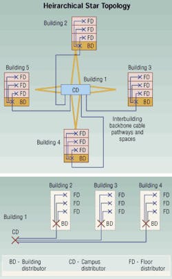
In the figure Hierarchal star topology (page 64), two levels of crossconnects are introduced resulting in multiple backbone crossconnects between FDs. This intermediate location is known as the building distributor (BD). ANSI/TIA/EIA-568-B.1 restricts the total number of "backbone" crossconnects to three. A backbone crossconnect is defined as crossconnecting one backbone cable to another.
In this example, a back bone crossconnect can be made at the CD or the BD but not at the FD. The FD is the crossconnect between the horizontal subsystem and the backbone cable or equipment in the telecommunications room (TR).
Once designers understand the standards topologies and their criteria for design, they can proceed with other aspects of the design.
The next aspect depends on the number of work areas in each building being served from the CD. A basic rule of design is to allocate a 10-sq. ft. space of usable floor space for each work area in the building when the actual requirements are not known. If the customer's requirements have been identified, then apply those in lieu of the 100-sq. ft. rule.
Examples of deviations from the standard rule of thumb are executive spaces and telemarketing centers. Most executives have office areas that far exceed 100 square feet. To the contrary, telemarketing centers typically allocate a 24-sq. ft. space for each telemarketing employee. From these examples, you can determine that executive spaces can be less dense and call centers can be substantially denser than the normal rule of thumb. If designers don't take these conditions into consideration, the design may be flawed, resulting in a lack of backbone facilities during cutover.
When using the basic rule of thumb, designers must calculate the gross square footage of each floor in the building. The building's core area must then be identified and subtracted from the gross square footage of each floor. After that, the TR can be sized and accounted for, and then the intrabuilding pathways can be designed to house the required cables serving each floor.
The traditional rule of thumb for copper pair allocation is 1.5 to 2 pairs of "voice" 100-W twisted-pair 24 AWG backbone cable for each work area (WA) served. This may vary by organization (BICSI, SP, AP, CLEC, etc.). For optical fiber cable, there is no specific recommendation in intrabuilding design.
The importance of designing the intrabuilding backbone system first becomes evident when the required backbone pathways have not been designed into the structure. When pathways are congested or undersized, high-pair-count cables may have to be placed in the building and spliced to stub cables that extend the cable counts from the backbone cable to each TR. This will require developing a splicing sequence and alteration of design principles so that the allocated pathways can be used.
Designing inside out
Each building on the campus must be designed from the inside out. The intrabuilding backbone must be designed for each building, and then a cumulative design must be rendered for the interbuilding backbone system.
This cumulative design incorporates all of the pair requirements in the intrabuilding backbone system and transfers them to the interbuilding system. So, if you had four buildings cabled back to a single-story building, the cumulative effect of the pair requirements would result in several large cables being placed from the CD in the single-story building to the BD in the individual five-story buildings.
This would result in having to plan taper points in the cables, as well as splice locations, splice types, modules to be used, and splicing methods inside of the enclosures.
In addition, other splicing design parameters include:
- Distribution cable;
- Feeder cable;
- Work location identifiers;
- Placing options vs. splicing;
- Straight splice;
- Butt splice;
- Branch splice;
- Binder group identification;
- In-line vs. fold back method;
- Splice module identification;
- Testing splices ;
- Closure selection and installation;
- Splice case identification;
- 100 ½ twisted-pair media selection;
- 75 ½ coaxial media selection;
- Optical fiber media selection.
The evolution of the splice
The telecommunications industry was established upon the invention, not of the telephone, but of the telegraph. The original configuration of a telegraph circuit was to use a single wire connecting two telegraphy devices together. Earth became the ground return path to establish the circuit. But because of the noise introduced and the tremendous resistance of the earth, this was not satisfactory. So, a second conductor was introduced.
These conductors were uninsulated and solid, supported on insulators, mounted on poles. Air was the dielectric between the two conductors. At specific intervals, the conductors were switched by transpositioning the conductors using special insulators and brackets. This, in effect, created a twisted-pair of conductors.
After Alexander Graham Bell invented the telephone, a number of "telephone companies" were founded to provide service. Poles became so crowded that virtual pole farms were erected in towns and cities to connect the various subscribers. A better way had to be developed. As a result, telephone cables were invented.
The first cables were solid-core conductors insulated by an oil-impregnated silk cloth covering. Later, rubber insulation was developed, followed by paper- and pulp-insulated cable. Plastic-insulated cable was developed after World War II.
Lead pipe was first used as the cable's outer jacket. Conductors were pulled into the lead pipe, which was hammered down to size over the conductors. Lead pipe allowed the use of pulp and paper insulation for the conductors. Sometimes, a jute outer protection was placed over the lead pipe after it was hammered onto the cable.
Lead-tin and lead-antimony were then developed as cable jackets. Lead could be extruded directly over the cable assembly, speeding up the manufacturing process and allowing extended lengths of cable to be developed.
Dry paper was placed over the individual conductors via one of two processes. One was to overwrap the individual conductors using a spiral wrap of paper. The second process saw the paper placed longitudinally along the conductor's entire length.
The Bell System developed a process that allowed a paper pulp to be deposited onto the entire surface of the conductor, resulting in a pulp cable assembly. This process required that the relative humidity inside the cable jacket be kept less than 4% to allow for minimally acceptable electrical transmission factors. (When humidity increases, it causes the insulation resistance to decrease, resulting in an increase in conductance and mutual capacitance.)
Problems with lead sheathing resulted in cable jacket breaching, caused by rodents gnawing on the aerial and underground cables, the wind swaying and stressing the cable, and even routine digging with a shovel. These contributing factors allowed moisture to penetrate the sheath and create electrolysis to set up between conductors inside of the cable. Paper/pulp and water don't mix.
Cable repair personnel were called in to locate the sheath break and to repair the pairs damaged by the moisture intrusion. Once they opened the lead sheath, the defective pairs were dried and then spliced to remove the defective section of conductor. It was accomplished by splicing in a small section of individual conductor between the interrupted point(s) of an affected conductor.
The repair technician stripped the insulation from the damaged conductor on each side of the damaged point. It sometimes resulted in the removal of a short length of the conductor. (The length to be removed was usually determined by how long the electrolysis had persisted at that point.)
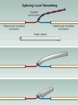
The new conductor was prepared by having a similar length of insulation removed on each end and then joining the pairs. The bare copper conductors (approximately 2 inches) were twisted together by hand, or soldered. A paper/cotton sleeve was then placed over the twisted conductor. The sleeve was then folded back in half, stabilizing the splice and preventing sleeve displacement.
In the early 1950s, the Bell System developed plastic insulated conductors (PIC) for cabling. This reduced the problems caused by paper and pulp insulation, and made way for development of a plastic-extruded jacket over a shield-manufactured over the pair bundle (binder groups). Plastic for the dielectric improved the transmission parameters and moisture resistance. Since plastic melts when heated, twisting and soldering the spliced conductors was no longer an option.
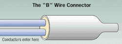
Many different connectors were developed and tried for splicing PIC conductors. Most proved unsatisfactory and a maintenance headache. Most were not insulation displacement connector (IDC) technology, and resulted in poor connections (high resistance). They also did not provide strain relief for the conductors in the splice. In addition, these connectors were either single-conductor or single-pair splices. One of the most damaging splice connectors for cable plant was the "B" wire connector. This device was used regularly on PIC cable both inside and outside of the Bell System until its discard in the early '70s. This connector has resulted in major physical plant problems as well as significant rehab money being expended to restore a plant to usable condition.
Today, there are newer types of single-wire, single-pair IDC connectors that provide positive contact inside of the connector, and performance that is rated as high as Category 5. They are not widely accepted as a valid splicing mechanism, however, except for low pair-count cables or repair splices.
Most high pair-count cable is spliced using 25-pair modular connectors. In 1960, 3M developed the MS< 25-pair splicing modules. By the mid-'60s, AT&T developed the 710 series 25-pair modules. Both of these splicing technologies proved successful in different arenas of telecommunications. 3M was successful in the contracting market and the RUS (REA) market. AT&T, meanwhile, implemented its 710 modules in the Bell System. Because of telecommunications deregulation and other factors, however, AT&T sold the rights to the 710 system to PSI in 1998.
In 2000, 3M bought PSI and along with it the right to manufacture and distribute the 710 system. Thomas and Betts make a slightly different version of the 710 tools, and markets them in competition with 3M. Today, most splicing is done by the contracting industry. Even many former Bell Companies contract out their splicing work because it is less expensive in both time and money.
Vic Phillips, RCDD and BICSI master instructor, is principal of Compass Telecommunications Consulting Corp., Florence, SC. You can contact Vic at [email protected].

