The manufacturing process is a determining factor to a multimode fiber's ability to handle high–speed parallel–optic transmission.
by Rich Pimpinella and Gaston Tudury
To support the changing and fast–growing bandwidth demands of business–critical data centers and Internet service providers, the Institute of Electrical and Electronics Engineers (IEEE; www.ieee.org) is developing a standard (802.3ba) that will support data rates for next–generation Ethernet networks. The standard, scheduled for ratification by mid–2010, is being written for fiber and copper cabling solutions and will cover both 40– and 100–Gbit/sec speeds.
To meet future high–speed demand for 100–Gbit/sec and above, data communications will likely employ multi–lane technologies, with each lane carrying a portion of the aggregate channel data stream. The advantage of multi–lane systems is that each lane operates at a much–reduced data rate.
The prospect of deploying multi–lane optical interconnection for next–generation Ethernet has gained much attention and is raising concerns about fiber channel "readiness" to support higher speeds. So, let's examine the key performance parameters affecting multi–lane transmission over multimode fiber as proposed for40– and 100–Gigabit Ethernet (GbE) channels, and how they relate to channel performance.
Multi–lane technologies
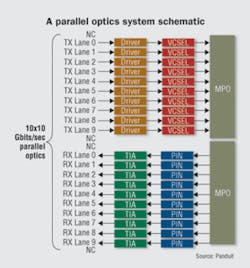
There are two primary methods of implementing multi–lane optical interconnection: wavelength division multiplexing (WDM), in which discrete optical wavelengths are coupled into a single optical fiber; and parallel optics, in which discrete transceivers communicate in parallel over multiple fibers. For communications requiring a 10 or 40–km reach, WDM over singlemode fiber (SMF) is the technology of choice for the new IEEE standard.
In short–reach applications, however, such as data centers, multi–lane parallel optics solutions over multi–mode fiber (MMF) will be specified. This approach is designed to leverage existing investments in high–grade OM3 fiber media while making provisions forextended reach or performance fibers. The MMF reach objective is, as this is being written, 100 meters. The reach will likely be extended to 150 meters over OM3 fiber and 250 meters for MMF, having an effectivemodal bandwidth (EMB) of at least 4,700 MHz·km (to be specified as OM4).
Because 40– and 100–GbE data traffic will be carried over parallel lanes of 4 or 10 discrete fibers, respectively, differ–ences in bit transport time over individual fibers must be kept to a minimum to ensure that multi–lane data traffic can be resynchronized at the receiver. Ideally, bits transmitted through a fiber ribbon array arrive at the receivers at the same time.The difference between the fastest and slowest bit arrival time in a multi–lane link is called skew. More skew requires more electronic processing to correct for skew, resulting in higher power dissipation and latency.
Performance parameters
The total skew in a multi–lane optical channel is affected by intermodal and chromatic dispersion, differences in fiber length, and deviations in refractive index. Some of these parameters are inherent to optical fibers and may be caused by process variation or stress in the individual fibers during the manufacturing process. The better the fiber manufacturing process and the tighter the control of process parameters, the better the quality and the more consistent the optical fiber.
To ensure that an OM3 (or OM4) cable will support parallel optics for 100–GbE and above, each of the following parameters must be well controlled:
• Intermodal dispersion: Different modes traversing different optical paths in the MMF spread in time, causing pulse broadening. The parameter used to express pulse broadening due to intermodal dispersion is differential mode delay (DMD). For a fiber to be classified as OM3, the DMD measurement must comply with one of six DMD mask templates specified in TIA–455–220–A and IEC 60793–1–49. DMD is measured by launching a test pulse into a MMF at highly controlledradial positions across the fiber core, from the core center to the cladding region. From DMD measurements, you can calculate the effective modal bandwidth (EMBc) of the fiberexpressed in units of MHz·km. (The EMB of a fiber isspecified as 1.13 times EMBc.)
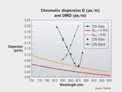
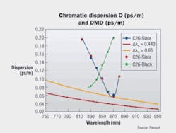
• Chromatic dispersion: When light of different wavelengths propagates in a material, it does so with different velocities.Vertical–cavity surface–emitting lasers (VCSELs) used for multimode fiber have a finite spectral width and, as a result, a pulse of light containing spectral content will be dispersed. Chromatic dispersion describes this broadening of the pulse width and has the effect of reducing signal quality, thereby degrading link performance. To measure chromatic dispersion, you adjust the wavelength of the DMD measurement system and analyze the wavelength dependence for a given propagating mode. This test data can then be used to calculate intermodal dispersion and chromatic dispersion and, when compared against other fibers, total skew.
• Pulse delay: The velocity of light is determined by therefractive index of the medium. Stress introduced during the manufacturing or cabling process, or during installation, can result in variations in refractive index from fiber to fiber, causing bits to arrive at the receivers at different times. In addition, any variation in individual fiber lengths will result in large differences in bit arrive times. The relative difference between pulse arrival times at the receiver is called pulse delay.
Certifying at high speeds
Using a high–resolution DMD measurement system, Panduit analyzed intermodal dispersion, chromatic dispersion, and pulse delay in a 12–fiber OM3 ribbon cable typical of the type that might be found in a data center. Initial bit error rate (BER) system test measurements and DMD analysis of each of the individual fibers showed that two of the 12 fibers were not, in fact, OM3 quality. Upon further investigation, we determined that the DMD system used by the manufacturer to characterize these fibers made inaccurate measurements.
We then took easurements for time–of–flight and for intermodal and chromatic dispersion, and totaled each of these measured contributions to skew. This resulted in two significant conclusions. First, the largest contribution to skew is the time of flight, which is independent of fiber bandwidth. Second, although not all fibers in the cable met OM3bandwidth requirements, the maximum time–of–flight difference occurred between two OM3 fibers.
In other words, these results indicate that use of highEMBc fiber cables (i.e., OM3 and above) will not auto–matically guarantee low skew or high performance. Certification testing of the ribbon cable is necessary to guarantee 40/100–GbE performance.
Fiber certification testing cannot be done with commercially available equipment, and it cannot be assumed that high–bandwidth fiber will mask inefficiencies due to dispersion and skew. It is the vendor's responsibility to test the fiber media towards controlling uniform pulse delay and optimizing skew, so contractors and designers can specify fiber media that enables signal integrity across the channel.
How it affects you
We have described parameters (i.e., dispersion and skew) that affect MMF performance at higher data rates, and shown how these measurements can be used to characterize differences in fiber quality and certify fiber media capability. But the key to assuring multi–lane 40/100–GbE parallel–optic signal integrity is strong control over the fiber–media manufacturing processes—the better the fiber–manufacturing process (raw fiber, ribbonization, andcabling) and the tighter the control of process parameters, the better the quality and the more consistent the optical fiber.
Through our testing processes, Panduit has identified that control over one of the key parameters being developed for high–bandwidth MMF systems–skew–is not sufficient to ensure high–bandwidth performance, as there is not a close correlation between high EMBc values and skew. Also, although the maximum allowable skew for 100GBase–SR10 remains to be specified, it is important to note that transceivers can correct for skew and that skew ultimately may not be identified in the standards as a critical parameter.
As customers develop future–ready cabling plants, they need to payparticular attention to the quality of the fiber beinginstalled to guarantee future performance. Best–in–class cabling vendors will be able to certify MMF for reliable multi–lane 40/100–GbE performance through accurate characterization of fiber bandwidth, certification of BER system performance of raw fiber and cabledmedia, and establishing specifications for fiber mediapartners towards retaining lane–to–lane skew.
RICK PIMPINELLA, Ph.D. is the fiber research manager and GASTON TUDURY, Ph.D. is a fiber research engineer at Panduit Corp. (www.panduit.com).


