From the January, 2012 Issue of Cabling Installation & Maintenance Magazine
Test methods and the market’s commercial realities cast a favorable light on interoperability issues.
By Jeff Englebert, Corning Optical Fiber
Since their introduction in 2009, bend-insensitive multimode fibers (BIMMF) have gained broad acceptance in the enterprise market. The combination of superior bend performance and compliance with existing 50/125-µm multimode fiber specifications has made it the multimode fiber of choice in the most demanding application spaces. As a result of its prevalence in the marketplace, BIMMF has encountered its share of dissenters. Claims have been made about the performance of these fibers and their compatibility with legacy fibers in the installed plant. Typically the claims are based on seemingly sound principles, but they omit some facts. Clear, concise and factual information is essential to cutting through claims and gaining an understanding of the reasons for choosing BIMMF for high-speed premises applications.
I suspect many of you have heard these claims in some level of detail. This article will provide some facts you did not hear in those arguments, reminiscent of Paul Harvey’s radio segments “The Rest of the Story.”
Two primary factors are typically cited as concerns relative to compatibility—the potential for elevated insertionNA: Acceptance and understanding
Perhaps the single most pervasive allegation about BIMMF is that its insertion losses are elevated, particularly in links that incorporate legacy 50/125-µm multimode fibers. The claim is fundamentally rooted in the difference in numerical aperture between BIMMF and legacy fibers.
One of the multimode fiber attributes that can be modified to affect its macrobend performance is numerical aperture (NA). The numerical aperture describes the fiber’s angular ability to accept light. A higher NA indicates a greater ability to receive and retain light in the fiber core. One way to improve the macrobend performance of a multimode fiber is to increase its NA through a higher core refractive index delta. Therefore, one type of BIMMF may be created through a higher core delta, which will increase the NA of the fiber. Rather than employing a simple increase in core delta, however, some BIMMFs typically use a lower index trench around the fiber core, which confines the optical power when the fiber is subjected to bends. The lower index trench also tends to increase the NA of the fiber. As a result, the average NA of BIMMF is slightly higher than that of legacy fibers, but it remains within the fiber specifications of 0.200 ± 0.015.
The potential mismatch in numerical aperture between BIMMF and legacy fibers can result in insertion loss. Insertion loss due to numerical aperture mismatch is defined as follows.
Therefore, a mismatch in numerical aperture between any two fibers, whether BIMMF or legacy fibers, will theoretically result in insertion loss when the NA of the receiving fiber is less than the NA of the launch fiber. The implication to the BIMMF design is apparent; its higher NA and the lower NA of legacy fiber translates into NA mismatch, which could cause higher insertion losses.
The higher nominal NA value for BIMMF lends credibility to the allegation that insertion losses of heterogeneous links will be higher than homogeneous legacy links. A more in-depth look at NA and its measurement method is required to assess the validity of this claim. The NA value that is used in conjunction with this claim is obtained via an industry-defined measurement standard—IEC 60793-1-43. The standard requires the use of an overfilled launch condition (OFL) to measure the far-field (transmitted power as a function of angular position) characteristics of a two-meter fiber sample. There are two key points of this measurement to consider. The first point is the launch condition that is used to probe the output characteristics—the OFL. Second, the output characteristics of the fiber are used to define its ability to receive light. Both of these points reveal why the specified NA value, as defined by the measurement standard, will not yield an accurate theoretical estimate of the coupling loss between heterogeneous multimode fibers in an enterprise system.
The OFL was originally conceived as a means to drive agreement between measurement organizations. A spatial (radial) and angular (NA) overfilled launch was required to ensure that different organizations were using similar launch conditions for the measurement of key multimode fiber attributes, such as core diameter, bandwidth and numerical aperture. Therefore, an OFL is a laboratory-based launch condition that was defined by inter-facility measurement agreement rather than as a means to evaluate these attributes relative to system functionality. In reality, the OFL does not adequately define an actual launch in today’s multimode fiber systems. An OFL-based NA tends to be significantly higher than the NA that is produced under launch conditions that are more consistent with typical sources in today’s multimode systems. In fact, even LEDs, which are representative of the slow-speed systems of the past, do not generate a standard-compliant OFL. Therefore, a theoretically predicted NA loss due to different fiber NAs at the joining point will be overstated. A more practical means to describe the NA of a fiber in today’s transmission systems is needed so the impact of NA mismatch on insertion loss can be better understood.
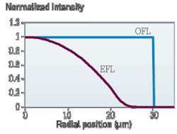
A more practical launch condition for the assessment of NA mismatch and connector insertion loss is represented by the encircled flux launch (EFL). The EFL, defined in IEC 61280-4-1 Annex E, closely represents the worst-case launch characteristics that will be experienced in today’s enterprise systems. This launch condition is designated for field attenuation measurements, which includes connector insertion loss and macrobending loss measurements. Because the EFL is the prevailing standard for as-installed field attenuation measurements and has direct linkage to system functionality, it is most appropriate to conduct any insertion loss studies with a standard-compliant EFL. A comparison of the OFL to the EFL is presented in Figure 1. The plot displays the significant difference in intensity associated with the two conditions, particularly in the outer areas of the fiber core.
To this point, the discussion has focused on the theoretical impact of NA on insertion loss that has been the basis for the claims against BIMMF compatibility. To determine the validity of these allegations, a detailed experiment was designed to evaluate the coupling loss of BIMMF—specifically our own multimode fiber with the trade name ClearCurve—with itself and with legacy 50/125-µm multimode fibers. The experiment included BIMMF and legacy fibers that spanned a range of core diameters and numerical aperture values. Jumper lengths of 2, 10 and 30 meters were included to ensure that practical application space conditions were represented. The jumpers were terminated with standard-tolerance LC connectors from an external organization. A combination of homogeneous (all legacy or all BIMMF) and heterogeneous (legacy/BIMMF) links were randomly constructed from these jumpers at each length and their EFL-based insertion loss was recorded. Six-jumper links were constructed and the link insertion loss was evaluated after the addition of each jumper.
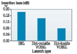
Figure 5: Average insertion loss with VCSELs for homogeneous links of 30-meter jumpers with BIMMF.
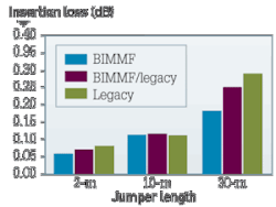
The results of the study, shown in graph form within this article, clearly indicate that the insertion loss of homogeneous BIMMF links is typically advantaged in comparison to legacy fibers. Figure 2 shows the average insertion loss of 12 different six-connector links consisting of randomly selected jumpers. The average insertion loss value at each length represents 72 different fiber/connector combinations. The EFL-based insertion loss data confirms that BIMMF has statistically comparable or lower insertion loss at the three evaluated lengths. The increase in measured loss with increasing length is predominantly due to the additional fiber length in the jumper.
The experiment was repeated with heterogeneous BIMMF/legacy fiber links. The results are presented in Figure 3. The average insertion loss of the links with BIMMF was comparable to or better than the average loss of the homogeneous legacy links. The results of the experiment show that BIMMFs are comparable with legacy fibers. There was no increase in insertion loss when the two fibers were mated in this simulated hybrid system.
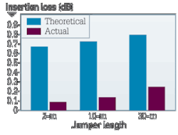
The results of this experiment were compared with the theoretical numerical aperture loss that is projected in the equation that appeared earlier in this article. The numerical apertures of the fibers that were used in this experiment were measured in accordance with the industry standard procedure and the theoretical loss for each mated pair was calculated. Based on the equation, the minimum insertion loss in the BIMMF-to-legacy direction would have been in excess of 0.5 dB. Conversely, the insertion loss in the legacy-to-BIMMF direction would have been close to zero because the receiving fiber’s NA was much higher than that of the transmitting fiber based on the OFL-based NA measurement value.
The actual results, shown in Figure 4, contradict the theoretical predictions. The average loss for the measured links should have been close to 0.7 dB based on the theoretical NA mismatch. In reality, the average insertion loss was significantly less than the theoretically predicted loss at all evaluated lengths. This confirms that the EFL, the prevailing standard launch for system loss evaluation, yields a much lower insertion loss than the theoretically based NA loss equations. This is due to the fact that the NA measurement is based on OFL, which exaggerates how power is coupled into the fiber of actual multimode systems.
As a final check, insertion loss measurements were conducted with commercially available 10-Gbit/sec vertical-cavity surface-emitting laser (VCSEL)-based transceivers. Homogeneous BIMMF links were constructed with the 30-meter jumpers because longer length was the assumed worst-case condition. Insertion loss was measured with two different 10-Gbit/sec transceivers. One transceiver was selected specifically for its VCSEL “hot outside” characteristics—its encircled flux very closely resembled that of the EFL defined in IEC 61280-4-1. The second transceiver had a VCSEL that was “hotter inside” than the EFL and the other VCSEL. As Figure 5 indicates, the average insertion loss results for the “hot outside” VCSEL were slightly better than those generated from the standard-compliant EFL. The “hotter inside” launch had the best average insertion loss values. The results clearly show that BIMMF is compatible with the sources that are used in today’s most advanced high-speed multimode systems.
During this experiment, in excess of 1,000 individual insertion loss measurements were conducted. A wide array of jumper lengths, fiber characteristics and light-source characteristics were studied. All of the results clearly demonstrate that BIMMFs are compatible with legacy fibers and well-suited for deployment in homogeneous and heterogeneous systems. The hard data dispel the allegation of fiber incompatibility.
Leaky modes holding water?
Another recurring claim about BIMMF pertains to “leaky modes.” A variety of compatibility-related claims, including numerical aperture and core diameter variation with measured sample length, are attributed to “leaky modes.” At first glance, the thought of a change in measured core diameter and numerical aperture as a function of sample length seems daunting. The implication associated with the observed change is that insertion loss or other fiber characteristics will also change with length.
In reality, the “leaky mode” effect is a measurement artifact associated with the overfilled launch condition that is used to measure certain attributes. The potential to experience “leaky modes” is not necessarily restricted to BIMMFs. They have been cited previously in literature on conventional multimode fibers. As noted previously, the OFL is a laboratory launch condition that was developed for inter-organizational measurement agreement. The OFL does not provide a practical indication of system functionality because it is not representative of the launch conditions that today’s high-speed transmission sources generate. Today’s transmission systems have worst-case launch conditions that are more representative of the encircled flux limited launch that is defined in IEC 61280-4-1. Therefore, admonitions about detrimental effects of “leaky modes” are unsubstantiated. They are akin to warning signals on a long-vacant set of railroad tracks—a risk may be indicated, but there is no practical concern.
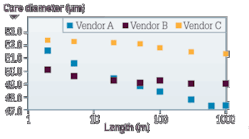
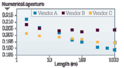
A series of conducted measurements demonstrated that “leaky modes” are a phenomenon that is uniquely related to the use of an overfilled launch. Different BIMMFs from several different vendors were obtained and the OFL-based numerical aperture and core diameter values were obtained at sample lengths from 2 meters to 1 kilometer. The responses of the two attributes were plotted as a function of length. (Results are presented in Figures 6 and 7.) All BIMMFs demonstrated some degree of core diameter and numerical aperture variation as a function of length. The experiment was repeated on an adjacent piece of each fiber, except this time an IEC 61280-4-1-compliant encircled flux limited launch was used as the launch condition for the measurements. (Those results are presented in Figures 8 and 9.) The results demonstrate that the EFL launch did not include a length-dependent response in core diameter or numerical aperture. The core diameter and numerical aperture vary with length only when an OFL is used. Therefore, “leaky modes” are attributable to the launch condition and are not fundamental to BIMMFs. Because the EFL is representative of a worst-case launch condition that could be expected in an actual system, this confirms that “leaky modes” do not pose a functional issue.
The weight of the matter
Both the insertion-loss and length-dependency studies show that an EFL yields excellent performance. As noted previously, the EFL is intended to represent a worst-case “hot outside” VCSEL. Dissenters could claim that coupling offsets combined with a high volume of “hot outside” VCSELs could still present “leaky mode” or insertion loss issues with BIMMF. This possibility is considered to be very unlikely. First, standard tolerance connectors were specifically requested for these studies. Despite the standard tolerances, the insertion loss results are superior and not indicative of significant issues with excessive offset. Second, the population of commercially available transceivers appears to be centered between “hot centered” and “hot outside” as presented in Figure 10. This plot represents the encircled flux of more than 100 commercially available 10-Gbit/sec transceivers. Note that less than 10 percent of the population is more “hot outside” than Weight 4. By comparison, Weight 5 is closest to the EFL condition. Because Weight 5 is most representative of the EFL and a very small fraction of transceivers have an encircled flux that approaches the EFL condition, the results of this study accurately represent today’s high-speed multimode applications.
More than 750,000 kilometers of BIMMF have been processed by 80 cablers and deployed globally in more than 20 countries. BIMMF continues to grow in popularity. Only a fully compatible, high-performance BIMMF would enjoy such success in the premises communications market.
Jeff Englebert is the manager of product engineering at Corning Optical Fiber’s Center for Fiber-optic Testing (www.corning.com/opticalfiber).


