Behind-the-scenes design engineering and manufacturing can greatly affect cords’ lifelong performance.
Rodney Throckmorton, Corning Cable Systems
As network transmission speeds increase in public and private networks, link loss budgets will continue to tighten, and performance of passive components such as patch cords will become critical to system integrity and reliability. Even though the TIA-568-C.3 standard specifies 0.30 dB per fusion splice and 0.75 dB per connector pair, most installers and end users would be greatly disappointed if actual performance was not ≤30 percent of these values. When purchasing patch cords or jumpers, the old saying, “You get what you pay for” often rings true. With the substantial investment required for a new 40/100-Gbit/sec system, does it make sense to cut corners by installing cheap patch cords for the last few feet? The answer is an emphatic “no,” and this article should give you a better understanding of why this is true.
Insertion loss (IL) and reflectance are the basic performance parameters of a connectorized cable assembly. These are readily measured in the field during system certification as well as problem troubleshooting. IL for discrete components or link loss for tip-to-tip systems can be measured using a light source and power meter, commonly referred to as an optical loss test set (OLTS). An optical time domain reflectometer (OTDR) can also measure IL or link loss, but bidirectional measurements are required to achieve accurate values, especially if a system has dissimilar fibers.
The axiom about getting what you pay for is not always true, unfortunately. Some contractors and users pay good money for fiber-optic patch cords but because those cords were not tightly controlled during manufacturing, they are of low quality.
Reflectance for discrete components or optical return loss (ORL) for tip-to-tip systems is typically measured with an OTDR. This is critical for applications such as analog and digital video where ORL less than 27 dB can cause instability in a laser source, resulting in poor image quality.
If patch cords provide the loss and reflectance performance needed, does this guarantee a robust and reliable system? What about connectors in a fiber distribution hub (FDH) that will experience temperature ranges of greater than 80 degrees Celsius (176 degrees Fahrenheti)? Will these be the cause of your next system outage? Here are a few more parameters that ensure reliability and quality required in patch cords.
Radius of curvature
The radius of curvature (ROC) is the radius of the ferrule endface measured from the axis of the ferrule. A radius between 7 mm and 25 mm is typical to provide the correct compressive force between two mated connectors. The internal spring in a connector exerts a predetermined force to compress and deform the ceramic ferrules and glass fibers, resulting in a contact footprint between 150 µm and 200 µm in diameter. If the ROC is less than 7 mm, this force is concentrated into a smaller contact footprint and the risk of shattering the glass fiber increases. If the ROC is more than 25 mm, the contact footprint increases and physical contact may be compromised, resulting in increased reflectance and insertion loss.
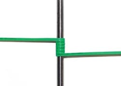
This standard jumper (green), when wrapped around an industry-standard 11-mm mandrel produces 1.1 dB of attenuation. Lack of process control during manufacturing or engineering and design flaws may produce a worse-performing jumper. But with standard fiber inside there is only so much improvement that can be made through design and engineering efforts.
To see the contact footprint, conduct this simple test.
Take two like connectors and an adapter sleeve to connect the two. Clean and visually inspect both connectors.
Touch the ceramic ferrule of one of the connectors to the side of your nose. This will transfer some body oil to the endface of the connector.
Lightly wipe the endface with a lint-free cloth.
Mate both connectors with the adapter sleeve.
Remove either connector and inspect with a 200x scope or probe. The contact footprint will appear as a circular pattern of small oil beads around the fiber. The eccentricity of the contact footprint is also an indicator of the magnitude and direction of the connector apex offset, which is described next.
The apex offset is the distance from the axis of the ceramic ferrule to the apex, or highest point, of the spherically polished endface. The apex can occur in any direction from the center of the ferrule but must be controlled to prevent loss of physical contact, resulting in increased reflectance and insertion loss. This is especially critical in uncontrolled environments such as the FDH or a cable TV node.
Position and cleanliness
The fiber position is the protrusion or undercut of the fiber endface relative to the ceramic ferrule at the axis of the fiber. This is also critical in maintaining the physical contact of two mated fibers. Too much protrusion may shatter the fiber, and too much undercut may result in loss of physical contact, resulting in increased reflectance and insertion loss.
ROC, apex offset and fiber position are all interdependent and acceptable values are well documented in IEC 61755-3-1. To control these parameters, they must be measured using a non-contacting interferometer. Many manufacturers do not have the equipment or capability to perform these measurements and maintain no control over these critical parameters. Testing programs to verify performance are detailed in TIA-568-C.3, Annex A.
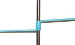
This jumper (blue), also wrapped around an industry-standard 11-mm mandrel, produces only 0.2 dB of attenuation. The difference between this jumper and the one pictured on the opposite page is that this one includes low-loss, ultra-bendable optical fiber. This type of fiber gives system designers flexibility in planning their loss budgets.
Then there is potential for endface debris and defects. Inspection with 200x or 400x magnification should be performed against an industry standard such as IEC 61300-3-35. Large defects such as scratches and pits can collect and transfer dirt to an opposing connector, sometimes creating additional defects. Cleanliness is critical to attaining acceptable IL and reflectance performance. Anytime a connector is mated or re-mated, it and the opposing connector should be properly cleaned.
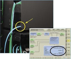
Shown here is a jumper with ultra-bendable performance in use. The yellow circle shows where the fiber has been pinched in a cabinet. With standard fiber, such a pinch can send network technicians on a lengthy and frustrating search for a loss source that has adversely affected network performance. As the inset test readout indicates, the macrobend in this jumper did not result in any system loss.
Parameters typically not measured
If that isn’t enough, here are several more design characteristics that can impact quality, overall performance and reliability. These characteristics typically are not measured during the manufacturing process.
- The epoxy selection and preparation must ensure no air voids leave exposed bare fiber within the connector. Exposed bare fiber can result in microbending loss during temperature variations.
- The crimp dimension for strain relief must be controlled, or macrobending can be introduced. Vendors with little process control may experience changes in material or wall thickness of the crimp band that can impact connector performance.
- If a heat-shrink is used for jacket retention, proper heating will ensure the fiber is free to move within the jacket during mating. If the shrink is too tight, the fiber as well as the ferrule will be locked into position, risking shatter of the fiber endface.
- Fit of the ferrule holder key to the connector housing controls how much the ferrule can rotate and is especially important with APC connectors that mate to an opposing angled ferrule. Too much play can result in variability in IL and reflectance.
One final consideration is the use of bend-insensitive fiber in patch cords. These fibers, available in both singlemode and multimode, significantly reduce issues with routing bends or pinching that many times are difficult to locate, even with a visual fault locator. The frustration of troubleshooting a system for hours, just to locate a tie-wrap that was pulled too tight, can be eliminated. These fibers have brought the industry closer to eliminating installation errors and ensuring future activity around a rack or in a cabinet does not result in downtime and needless, costly hours of troubleshooting.
Fiber patch cords may look the same on the outside, but what happens on the inside, particularly during engineering and manufacturing, can greatly affect their performance and therefore network performance. Some design and engineering characteristics are measured during manufacturing; others typically are not.
With numerous sources from which to purchase path cords, understanding the many parameters that define reliability is paramount to selecting a quality product. A significant amount of engineering design and manufacturing support is required to ensure tight control of these parameters. Additionally, the capability to demonstrate performance through service-life testing is important, not only to verify compliance with minimum criteria but to gauge success of design and process improvements. If the price of a patch cord looks too good to be true, it is likely that little if any control of these parameters exists. When selecting patch cords, these critical parameters, along with price, should be factored into the decision so that you truly “get what you pay for.” But more importantly, the product you install will provide your customer with reliable service.
Rodney Throckmorton is senior applications engineer with Corning Cable Systems (www.corning.com/cablesystems).


