Installation costs for fiber-optic cable often exceed the cost of materials, so it makes
sense to test the integrity of the cable at each step of installation.
Jim Hayes, Fotec Inc.
Although fiber-optic networks differ significantly from copper-based networks, the methods for testing and troubleshooting them are very similar. The techniques can easily be mastered by technicians with some basic training in fiber optics and network testing. The procedures discussed here have been thoroughly field-proven in thousands of installations, and they will help installers locate problems in time and at the source.
To thoroughly test fiber-optic cabling plant requires that you test it three times. You should test the cable on the reel for continuity before installing it to ensure that no damage was done in shipment from the manufacturer to the job site. It is generally sufficient just to test for continuity, since most fiber is installed without connectors and then terminated in place, and poor connectors are the most common problem to be uncovered by testing for loss.
After termination, test each segment of the cabling plant individually as it is installed, to ensure that each connector and cable is good. As a final check, test each end-to-end run, from the wiring closet to end-user equipment.
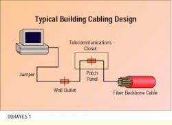
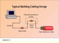
Typical fiber-optic cabling plants are composed of a backbone cable connecting patch panels and several short jumper cables that connect the equipment to the cabling plant. Building and campus systems usually have the backbone fiber terminated in wiring closets; short jumpers connect to wall outlets or directly to the equipment. These installations often have no splices at all, since distances are short.
Testing the complete cabling plant is done per a standard test procedure, Optical Fiber Systems Test Procedures-14. This procedure covers the peculiarities of multimode fiber in detail. In fact, it was written to address the problems of controlling mode power distribution in multimode cables but, with the exception of mode power distribution errors, the same procedures apply to singlemode fiber.
For multimode fibers, testing is usually done at both 850 and 1300 nanometers, using light-emitting diodes. This proves the performance of the cable for every data communications system, including fiber distributed data interface and enterprise systems connection, and meets the requirements of all network vendors. For singlemode fiber cables, testing is usually done at 1300 nm. Sometimes 1550-nm testing is also required to show whether the cable can support wavelength-division multiplexing at 1300 and 1550 nm, for future service expansion. In addition, 1550-nm testing can show microbending losses that are not obvious at 1300 nm, since the fibers are much more sensitive to bending losses at 1550 nm.
If cabling plant end-to-end loss exceeds total allowable loss, the best solution is to retest each segment of the cabling plant separately, checking suspect cables each way, since the problem is most likely a single bad connector or splice. If the cabling plant is long enough, an optical time-domain reflectometer may be used to find the problem. Bad connectors must then be repolished or replaced to get the loss within acceptable ranges.
Not long ago, OTDRs were used for all testing of installed cabling plants. In fact, printouts or pictures of OTDR traces were kept on record for every fiber in every cable. Today, the power meter and source (or optical-loss test set) have replaced the reflectometer for most final qualification testing, since the direct loss test gives a more reliable test of end-to-end loss than does an OTDR.
Do not use an OTDR for measuring end-to-end loss. It does not accurately measure actual link loss as seen by the transmitters and receivers of the fiber-optic link. As normally used, the OTDR does not count the end connectors` loss because it uses a laser with very restricted mode power distribution, which minimizes the loss of the fiber and intermediate connectors. Finally, the difference in backscattering coefficients of various fibers leads to imprecise connector loss measurements.
However, you may have to use an OTDR to find bad splices or optical return loss problems in connectors and splices in singlemode cabling plant. Only with a reflectometer can optical return loss problems be located for correction. Typical backreflection test sets give only the total amount of backscatter or return loss; they do not give information about the effects of individual components, which is necessary to locate and fix the problem.
If an OTDR has high enough resolution to record short, individual cable assemblies, it can also be used to find bad connectors or splices in a high-loss cabling plant. However, if the cables are too short or the splices too near the end of the fiber (as is often the case with pigtails spliced onto singlemode fiber cables), the only way to localize the problem is to use a visual fault locator, preferably a high-powered, helium-neon laser type, which can shine through the jacket of typical yellow or orange PVC-jacketed single-fiber cables. This method of fault location is easiest with single-fiber cables that have yellow or orange jackets, because these are more translucent to laser light.
Testing networks
To test network cables, use a fiber-optic test kit, which includes a fiber-optic power meter and an LED or laser source. The source should be of the same type and wavelength as the transmitters used in the network being tested. Adapters provide the interface to the connectors used with the network. You will need test cables as launch and receive jumpers for testing the network cables, and a connector coupling kit to interconnect the test jumpers with the cables to be tested.
Connectors and cables should be handled with care. Do not bend cables too tightly, especially near the connectors, because sharp bends can break the fibers. Do not drop the connectors; they can be damaged by a blow to the optical face. Do not pull hard on the connectors because this might break the fiber in the back of the connector or cause pistoning if the bond between the fiber and the connector ferrule is broken.
If there is any question about the condition of the connectors, clean them before testing. Use a fiber-optic inspection microscope with appropriate stages to hold the connectors if there is any doubt about their cleanliness or physical condition.
In the installation and testing of fiber-optic networks, a problem routinely encountered is incorrect fiber-optic connections. A fiber-optic link consists of two fibers transmitting in opposite directions to provide duplex communication. It is common to find fibers switched, with the transmit fiber connected to a transmitter and the receive fiber to a receiver.
To avoid this problem, use a visual tracer to verify the proper connections. The tracer can be a flashlight (although it is hard to hold the fiber in place to couple enough light to see it), a modified flashlight, or even a microscope that will hold the fiber steady and couple an adequate amount of power into it. A special test source using a bright red LED, like those used in plastic fiber links, can also serve as a tracer. Shine the visible light from the tracer down the fiber and track the fiber through the cables and patch panels to the far end.
With a tracer, you can trace fibers for up to 2.5 miles (4 kilometers). In addition to tracing fibers, you can use the device to check continuity and find broken fibers in cables. Another recommended use is to check the continuity of every fiber in multifiber cables before installation to ensure that all fibers are functional. Installing a cable with bad fibers can be an expensive proposition. Visual tracers are an inexpensive, valuable tool for every member of the installation crew.
For singlemode cables, a more powerful tool is available --a high-power visible laser coupled to fiber. This visual fault locator uses a red laser --either helium-neon or diode --- with enough power to show breaks in the fiber through the jacket of the fiber. It is much more expensive than a simple fiber tracer, however.
Testing installed cabling plant
Fiber-optic networks are always specified to operate over a range of loss, typically called the system margin. Either too much or too little loss can be a problem. If loss is too high, the signal will be low at the receiver, causing a poor signal-to-noise condition in the receiver. If the loss is too low, the power level at the receiver will be too high, causing receiver saturation. Both these conditions will cause high bit-error rates in digital systems and poor analog signal performance.
Using a power meter and source, test the complete cabling plant for loss; include all individual jumper or trunk cables.Use the double-ended method, since system margin specifications include the loss of connectors on both ends of the fiber. If the end-to-end (transmitter-to-receiver) loss measurement for a given fiber is within the network margin specification, the data should be recorded for future reference. If the loss is too low, notation should be made that the fiber will probably need an inline attenuator to reduce receiver power to acceptable levels. If the loss is too high, it will be necessary to retest each link of the complete cable run to find the bad link.
Possible causes of high end-to-end link loss are bad connectors, bad splice bushings in patch panels, cables bent too tightly around corners, broken fibers in cables or even bad launch or receive cables or instruments. There are only two ways to find the problem: Test each segment of the cable individually, or use an OTDR if the lengths are long enough to be viewed with the limited resolution of this instrument.
Testing and troubleshooting networks
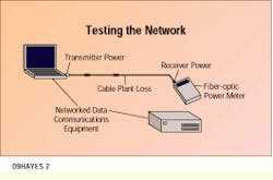
The installed network can be tested quickly and easily with a fiber-optic power meter. Set the network transmitter to transmit a clock output or other bit stream of known duty cycle. Set the power meter calibration on the proper wavelength and the reading units on watts. To test the received power --the most critical element in the network --disconnect the cable connector at the receiver, attach the power meter and measure the power.
If the receiver power is low, check the transmitter power by disconnecting the source jumper cable at the first available connector and measuring the power at that point. Alternatively, you can disconnect the cable at the transmitter and use a jumper that has been pre-tested and is known to be good to measure the coupled power. If the output is measured through a short network jumper cable (less than 30 feet), no compensation for jumper loss is necessary. For longer jumpers, some compensation for cable loss may be necessary.
If receiver power is low but transmitter power is high, something is wrong with the cables. They must be tested at every connection to isolate the bad cables or connectors. Starting from either the transmitter or receiver end, follow the network cables to every patch panel. Disconnect the connector and measure the power at each point. By making measurements in decibels, you can easily calculate the loss of the cable network to each point by subtracting successive readings.
If you note a larger-than-expected loss in the cable link, test the suspect cable using one or more of the following methods. If a cable has attenuation that is higher than specifications but still transmits light, check the connectors using a microscope to determine if they have been damaged and should be replaced. If the connectors look good, the best solution may be to replace the cable or switch to a spare. If a visual fault locator is available, use it to locate breaks in the fiber and find broken connectors. Under some circumstances, such as high loss in long jumper or trunk cables, an OTDR can be used to diagnose cable faults.
Transceiver loopback testing
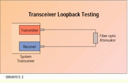
The data communications capabilities of the network can be tested with a loopback test. This test uses a calibrated fiber-optic attenuator placed between the transmitter and receiver on a piece of equipment to see if it can transmit data to itself. Many types of network equipment have diagnostics to do loopback testing. This loopback method tests the transmitter and receiver of the unit under standard data transmission conditions over the specified link loss budget.
Some data communications equipment can also institute an electrical network loopback test, where the loopback path is inside the equipment, looping back over the entire data link to the equipment on the far end of the link. If both ends of the link pass a unit loopback test but fail a network loopback test, the problem is in the cables, which then need testing.
Once installation is complete, the cabling plant is tested and network equipment is running smoothly, what is likely to go wrong in a fiber-optic network? Fortunately, not much. One of the biggest selling points for fiber optics has been its reliability. But there are some potential problems that can be addressed by the end user.
The biggest problem with the cabling plant is "backhoe fade." This happens when someone mistakenly cuts or breaks the cable, either when an electrician is working on cables inside a building or when an underground cable is dug up. Inside buildings, use orange- or yellow-jacketed cable instead of black or gray to make the fiber-optic cable more visible and distinctive. Short distances make OTDRs unusable inside, so a visual fault locator is necessary.
Outdoors, the best defense is to mark where cables are buried and bury a marker tape above the cable, to alert workers to the presence of cable below. Outside cable faults are best found by using a reflectometer to localize the fault, then having personnel search the area for obvious damage.
Another problem is broken cable just behind the connectors in patch panels. This is a difficult fault to find, but a visual fault locator is often the best way. Unless the jumper cables are quite long, a reflectometer won`t help at all.
Within the fiber-optic link, the most likely component to fail is the light-emitting diode or laser transmitter, because it is the most highly stressed component in the link. Lasers are feedback-stabilized to maintain a constant output power, so they tend to fail all at once. The power output of LEDs drops as they age, but the time frame is quite long --100,000 to 1 million hours. If there is no power at the receiver, the next place to check should be the transmitter LED or lasers, to isolate the problem to either the transmitter or the cabling plant. Receivers are low-stressed devices and highly reliable, but the electronics behind them can fail. If there is receiver power but no communications, a loopback test to see if the receiver is working is the best test of its status.
A typical building cable design includes a fiber-optic backbone that connects to patch panels in the wiring closets, and jumper cables that connect equipment to the cabling plant.
To test a fiber-optic network after installation, use a fiber-optic power meter to measure received power.
Transceiver loopback testing for data communications equipment can be performed with a calibrated attenuator set at the system margin.
Jim Hayes is president of Fotec Inc., (Boston). This article is excerpted from Fotec Inc.`s book, Fiber Optic Testing.


