James E. Hayes, Fotec Inc.
Problem
Inspection of the end surface of a fiber-optic connector is one of the best ways to determine the quality of the termination and diagnose problems. However, a single direct viewing of the fiber endface using a fiber microscope will not reveal all potential problems.
Solution
Using a microscope to inspect fiber involves three considerations?correct magnification, inspection of the appropriate area of the fiber endface and use of varied lighting to reveal different problems.
Procedure
1) Correct magnification for viewing connectors is generally agreed to be between 30 and 100 power. Lower resolution, such as that provided by a pocket magnifier or jeweler?s loupe, will not provide adequate resolution for judging the finish. Too high a magnification will exaggerate small faults.
2) Keep in mind that only defects over the fiber core represent a problem. Chipping of the glass around the outside of the cladding is not unusual and will have no effect on transmission performance. Likewise, scratches on the cladding only will not cause loss.
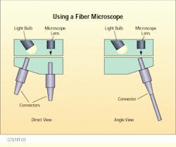
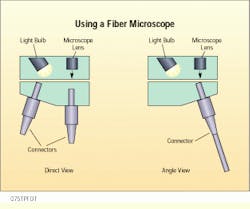
3) Inspect a connector in three ways:
?View the fiber end directly with side lighting. This lets you determine if the ferrule hole is the proper size, the fiber is
centered in the hole and the correct amount of adhesive has been applied.
?View the fiber end directly with side lighting and light transmitted through the core. This will reveal any cracks in the fiber end caused by pressure or heat during polishing.
?View the fiber end at an angle with lighting from the opposite angle. This lets you accurately inspect the quality of the polish and will show scratches. Shadowing caused by sidelighting and revealed by angular viewing enhances the contrast of scratches against the mirror-smooth polished surface of the glass.
A correctly terminated connector will have a smooth, polished, scratch-free finish. The fiber will not show signs of cracking or pistoning. (Pistoning occurs when the fiber either protrudes from the end of the ferrule or is pulled back into it.)
When fiber microscopes are used, different lighting angles reveal different kinds of problems.
James E. Hayes is president at Fotec Inc., Boston, MA. This tip is adapted from his book, Fiber Optic Testing.

