From the March, 2013 Issue of Cabling Installation & Maintenance Magazine
Commercially available equipment for the measurement and control of modal launch conditions is now coming onto the market.
By David Robinson, Arden Photonics
It has been known for many years that modal launch conditions have a major effect on the attenuation and bandwidth measured in multimode fiber-optic cabling systems. As the bandwidth of local area networks (LANs) is pushed ever-higher to meet demand, loss budgets are squeezed ever-tighter. This has led to an increasing amount of attention being paid to minimizing the insertion loss in multimode cables and connector components. For example, the IEEE 10-Gbit/sec short-wave specification over 300 meters (10GBase-S) specifies a maximum channel loss of 2.6 dB, which includes 1.5 dB for connector loss. So, for example, in a link with two connections the maximum allowed loss on each connection is 0.75 dB.
The biggest contributor to discrepancies in loss measurements is that different light sources may have very different modal launch conditions. The loss in a connection can vary by several tenths of a dB, depending on the modal distribution launched. Fortunately, standards bodies and equipment suppliers have responded to this challenge, providing launch specification that can ensure that measurement accuracy to 0.08 dB or better accuracy may be obtained, which is approximately one-tenth of the maximum loss allowed per connector.
Dealing with insertion loss
Multimode fiber cable has a major advantage over singlemode in short-haul applications, where its larger core diameter and higher numerical aperture (NA) mean it is much easier to get light in and out of the cable, and it is much more tolerant of imperfect splicing, connectorization and general cleanliness and handling. There are also cost benefits to installing multimode instead of singlemode networks, although these benefits lie within system equipment rather than the cable itself.
Insertion loss is arguably the most fundamental parameter of an optical fiber cable. It has been shown in a number of studies that the control, or lack thereof, of modal launch conditions is by far the most significant contributor to variations in insertion loss measurements in multimode fiber cables and connectors. If you measure the loss of a cable using two light sources with different modal launch conditions you will get different results. If the sources have the same launch conditions you will, within acceptable limits, get the same result.
It is important to point out that this says nothing about the accuracy of the insertion loss measurement. In a light source/power meter (LSPM) type measurement, the accuracy is determined by a number of factors such as stability of the light source, wavelength accuracy, quality of reference patch cords, noise in the detector electronics and other factors. If due care is taken, the measurement accuracy can be very good. The difference in loss measured here is real; the cable loss does actually depend on the modal distribution of the fiber.
Modal distribution and standards
So what exactly do we mean by "modal distribution"? Due to the electromagnetic properties of light, optical power traveling in a multimode fiber is restricted to certain discrete paths, or modes. In a typical multimode fiber with a 50-µm core operating in the 850-nm window, there are approximately 380 individual modes that can support light transmission. If every possible transmission mode in the fiber core is occupied the fiber is referred to as "fully filled." However, in a practical fiber this never happens. In any practical fiber, light transmitting in so-called "high order" modes is following a path that forces it close to the outside of the fiber core, making it susceptible to losses as the fiber is bent, or at small offsets such as at connectors or splices. By contrast, the "low order" modes stay close to the center of the fiber core are much less lossy. So using this simple analysis, it is clear that if the light that is launched into the fiber contains a lot of power in the "high order" modes, by the time the light exits the fiber it will have lost more power than a fiber in which only "low order" modes are present.
Therefore the solution is really quite simple. The loss measured depends on the balance of low and high order modes present at the input to the cable. So if all parties use the same launch distribution, loss measurements immediately become much more consistent. This leads to fewer discussions among fiber makers, cable makers and system installers, and fewer problems at the user's premises.
Control and measurement
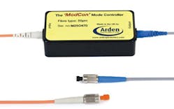
The optical fiber test and measurement community is working hard to make encircled flux (EF) controlled measurements a practical reality. Handheld test equipment that claims to meet TIA (Telecommunications Industry Association) and IEC (International Electrotechnical Commission) requirements is coming along. External EF "mode controllers" are also available; they offer a quick means of converting existing LED- (light-emitting diode) and VCSEL- (vertical-cavity surface-emitting laser) based test sets into fully compliant units. These external controllers simply replace the reference test cord on the output of a light source.
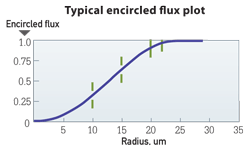
Of course, to standardize modal distribution we need to be able to accurately measure it. There are a number of ways to define and measure modal distribution, but over the last few years the telecommunications industry has moved toward a parameter called encircled flux (EF). EF has been used for several years for the characterization of fiber-pigtailed VCSELs and is described by IEEE (Institute of Electrical and Electronics Engineers) standards such as IEEE 802.3aq. More recently, the TIA and IEC have described the measurement technique in some detail, in TIA-455-203 and IEC 61280-1-4, respectively. As the name suggests, the method involves measuring the light intensity at a planar surface parallel to the optical axis of the fiber, for example at the surface of a connector. This two-dimensional map of the optical power is processed to calculate the optical power, or flux, contained in circles of increasing diameter, starting from the optical center of the fiber.
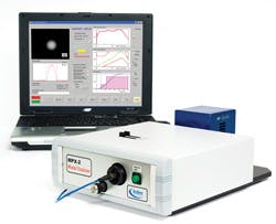
To successfully implement this technique, high-quality imaging optics and light-detection equipment is needed, as well as traceable calibration of the optical magnification. Fortunately, standards-compliant equipment is now commercially available that enables accurate, real-time measurements of encircled flux to be made.
International standards are now in place that define the modal launch requirements for measuring multimode cable plant. For example, IEC recently introduced a new version of IEC 61280-4-1, which defines in detail the encircled flux required in the measurement of cable systems. It defines the modal launch conditions as a series of upper and lower limits at various radial positions. While cable system makers and test equipment makers work hard to make their measurement equipment compliant, at the sharp end installers and users need quick and easy ways to ensure they are doing the right thing when testing and commissioning installed systems. To take care of this, services are available that can measure the encircled flux of test sources. If the sources are not compliant, mandrels may help, or commercially available modal controllers, which will produce the right launch conditions from any source.
To summarize, a major step has been taken by the industry to ensure that multimode fiber-based systems can continue to provide cost-effective solutions in short-haul, high-bandwidth applications. An international effort over a number of years has resulted in the release of appropriate standards, and commercially available equipment for the measurement and control of modal launch conditions is now available. This will lead to much-improved agreement between loss measured in different locations and using different equipment. ::
David Robinson is founder and managing director of Arden Photonics (www.ardenphotonics.com).
View CIM Archived Issues


