From the March, 2013 Issue of Cabling Installation & Maintenance Magazine
Integrated tapping technology allows administrators to monitor data center traffic without disrupting the production environment.
By David Kozischek and Michaela Iery, Corning Cable Systems
While the idea of "tapping" has obvious surveillance implications, making it desirable for analyzing potential security threats (denial of service attacks, hackers and more), many network administrators use port tapping to monitor the performance of their network and identify bottlenecks or other performance issues.
What is port tapping?
Port tapping is a method of monitoring traffic being transmitted and received along a link in a network; this monitored traffic is then analyzed. This can be done actively via electronic devices that replicate (also called "mirroring") the link's data and send it to a monitoring device. Or it can be done passively with a device that simply passes through all data and sends it simultaneously to both its intended recipient and to a monitoring device. In both instances, the monitoring device filters the data and sends it to various software tools for analysis, where it is then sent to application-layer software for use by network administrators.
The question often comes up, what does tap stand for? The answer is, nothing. The word is used in the surveillance sense (a "tap" on a phone line), meaning to connect into and monitor communications that are being transmitted.
Active and passive tapping
Active tapping, sometimes called mirroring or SPAN (switch port analysis), uses active electronics to duplicate a link's traffic and send it to a monitoring device. An active port tap requires that one of the switch ports be used solely for tapping, thereby reducing the number of ports that can be used for live network data.
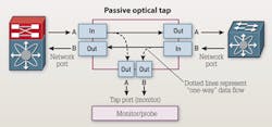
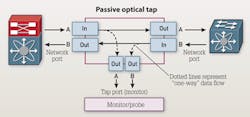
Passive tapping is considered "pass through," in that the link's traffic is not replicated by the switch in any way. Instead, the optical signal's power is divided, and the data stream sent simultaneously to both live traffic and monitoring electronics.
Passive tapping has the following five primary advantages over mirror tapping.
1) Passive taps deliver full duplex (transmit and receive) port monitoring at scalable data rates and do not require oversubscription. Mirror tapping requires a 2:1 oversubscription, as it fully replicates (duplicates) each port's data.
2) A passive tap is invisible to the network, passing all data through versus replicating it, and therefore creates no change to the timing of frame/packet interactions or extra burden on the production network, as mirror tapping does.
3) Mirror tapping requires an engineer to configure the switch to recognize a port as a tapping port. If this configuration is not disabled during a network refresh, a mirror port can be cabled to serve as a network port. This can create a "bridging loop," resulting in network performance issues. No such concerns exist with passive tapping.
4) Passive tapping truly lives up to its name in that it is completely passive—a physical connection that passes data through without switch configurations or programming.
5) Passive taps pass on all traffic in the link for monitoring; mirror ports may not receive corrupt data or improperly sized packets, eliminating a full picture of how the network is performing.
A closer look
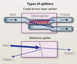
So what is a tap, exactly? Also called a "coupler" or "splitter," the tap is a passive device that takes a single input of optical light and divides it into two or more outputs. This splitting of the light can be accomplished in several ways, including fusing two or more fibers together (fused biconic taper being the most common method), or by the use of micro lenses, beam splitters or other reflective or guiding devices.
One characteristic of a passive tap is what is known as a split ratio—the percent of the output power that goes to the live traffic receiver compared to the percent that goes to the monitoring device. The most common split ratio configurations are 70/30 (70 percent going to the live traffic receiver and 30 percent going to the monitoring device), and 50/50. The existence of different split ratios allows flexibility for cable lengths and data rates, as well as the sensitivities of the electronics. This is largely an issue for multimode networks, as singlemode does not have distance or data-rate limitations.
Advantages of integration
An integrated tap is a module with a fiber-optic coupler inside that divides the optical signal into two outputs, one for live-link traffic and one for monitoring. The live traffic continues through the system link while the monitor traffic is sent to an active monitoring device.
The use of non-integrated passive tap devices demands an additional segment in the total channel link; the patch panel/module must connect to the tap device and then connect from that device to the switching and monitoring electronics. When monitored ports require changes, the link has to be temporarily disabled—including the live traffic—in order to make new physical connections between the ports to be monitored and the passive tap device.
With an integrated tap module, the module serves as both the "patch panel" and the passive tap device. The ports that are monitored can be changed without ever disrupting the flow of live traffic.
An integrated solution essentially creates a "zero-U" solution for network monitoring, as the monitor ports use the same footprint as the live traffic and require no additional space. With other passive tap devices, the monitor port takes up less space in the front of the rack that could be used for a live traffic port. In fact, the usual rule of thumb for other passive tapping devices is to add another 1U of rack space for every 8 to 16 ports that are tapped.
With an integrated solution, one rack unit can house 72 ports of live traffic at the front of the rack and monitor all 72 ports in the same footprint by having the monitored ports exit the rear of the module. This improved rack density means higher revenue generation per rack unit in data centers or storage area networks.
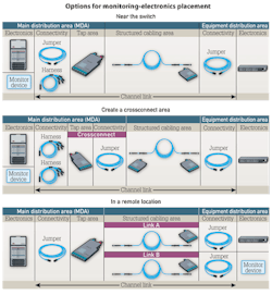
Three design options for the placement of monitoring electronics each provides a set of benefits, which we will describe here.
Locating the monitoring electronics near the switch to monitor all ports. The advantage of this design is that it can be integrated into the current cabling infrastructure (assuming the total channel link length is capable), swapping out a standard module with a tap module—either to begin passive tapping or to replace the current passive tap device with a higher-density, integrated module.
Creating a crossconnect to selectively monitor ports. The advantage of this design is that it replicates the ports in the structured cabling area to create a crossconnect area. This provides the advantage of additional design and network management flexibility. In addition, the use of harnesses from the tap module to the electronics enables them to be located farther away without cable pathway congestion, easily consolidating all of the monitoring equipment and allowing each piece of monitoring equipment to be fully utilized. And now, the monitoring electronics can be segregated from the switches, eliminating the risk of a patching error in the monitoring cabinet and potential downtime of the live network.
Locating monitoring equipment in a remote location. The advantage of this option is that it allows the monitoring electronics to be completely separated from the live network electronics, limiting network access to network administrators and monitoring access to data security/compliance administrators.
Monitoring network traffic is critical for many data center operators. The ability to monitor traffic without disrupting the production environment reduces downtime and increases productivity. New integrated structured cabling solutions allow more choices in types of deployments, offering flexibility and ease of deployment. ::
David Kozischek is enterprise market manager and Michaela Iery is global product commercialization manager with Corning Cable Systems (www.corning.com/cablesystems).
View CIM Archived Issues


