Barbara E. Thompson
Time-domain reflectometers test for a change in impedance (electrical resistance), which can be caused by cable damage, improper installation, change in cable type or water in the cable. Installers use metallic time-domain reflectometers to troubleshoot and measure all types of twisted-pair and coaxial cables.
The TDR transmits an electrical pulse down the cable, and when the pulse reaches the end of the cable-or a fault-part or all of the energy pulse is reflected back to the device. By measuring the strength of the energy reflection and the propagation delay (amount of time required for the reflection to arrive back at the device), the TDR can provide the installer with such information as the length of the cable or the location of cable breaks, shorts, opens or intermittent faults.
Two types of TDRs
The metallic waveform TDR displays the test data as a waveform and as a distance reading on its screen. The traditional TDR has a liquid-crystal display or cathode-ray tube screen to show the waveform of the pulse and any reflections caused by impedance discontinuities along the electrical pulse. Another type of TDR displays only a digital numeric readout of the distance in feet or meters.
"A digital TDR is good for testing cable faults such as opens and shorts," says Greg Hackbart, national sales manager at Riser-Bond Instruments. "It does not have as long a range, but it is simple to operate and less expensive than a waveform TDR."
Although both types of TDRs are equally accurate, the waveform TDR provides installers with more detailed information about the cable, but the simplified digital model is less expensive and easier to operate. When there are multiple faults in a cable, the waveform will show all of the discontinuities along the length of the cable; however, the digital numeric TDR will show only the distance to the first major fault.
The maximum range of any TDR depends on the particular model of TDR used. Accuracy, which also varies with the model used, is specified as a percent of the selected range.
Some TDRs have built-in printers or an RS-232 interface for downloading to a computer/printer. Smaller handheld TDRs for shorter-range applications may not include print capabilities.
For portability, size and weight of the TDRs are important, and some manufacturers offer handheld models. Other options available on different models are dual input connectors for two-line testing, DC operation, dual-cursor operation for measuring between points on the waveform, and storage capabilities that allow the operator to store waveform data both on- and off-screen.
Installers can use a TDR to verify and maintain a LAN. The TDR can be used to measure return loss of connectors, defective connectors, or such cable faults as opens, shorts, bends or crimps.
"If you`re testing an active network, you need a TDR," says Andy Poake, senior manager at Reliable Telcom Inc. (Kirklyn, PA). "We had a water leak in an underground cable and had to find out where it was. Using a TDR, you can actually watch your signal and see where any noise is being induced."
TDRs are used in all phases of a cabling system`s life, from construction and maintenance to fault-finding and restoration. The TDR can be used to:
Aid in measuring and verifying new or partial cable reels
Locate splices, crushed, pinched or kinked cables, opens and shorts in the cable, or water in the cable
Find inline components, such as connectors
Document or map cable networks
Identify bad terminations.
It is important, however, to test a cable from both ends, because a small fault may be difficult to identify if it is a long distance away. By testing at the other end of the cable, the installer may be closer to the fault and therefore be able to locate it more easily.
Installers today, however, are using another tool-the handheld cable scanner-to test new installations for Category 5 compliance. A few of these handheld scanners have a built-in TDR capability, but some in the industry believe this TDR function is not as precise as a metallic TDR for troubleshooting cable faults in an active network.
"For people who use Thinnet- or Thicknet-based systems, you need a waveform TDR," says John Breeden, product manager for the communications test business unit at Tektronix Inc. "Coaxial cable requires that you have a very tight control on impedance of the cable or the impedance change at a given point. For example, in a Thicknet system, a waveform TDR will give you information on whether the tap is installed properly, if the terminator is in spec, or if there are any kinks in the cable."
Variables in the Cable
[The following is excerpted from Riser-Bond`s Application Guide.]
Although the TDR is accurate, variables in the cable sometimes cause errors in distance measurements. The electric pulse transmitted by the TDR does not travel at the same speed in every type of cable. The size of the wire, type of insulation and external shielding affect the speed of the pulse.
A factor called the nominal velocity of propagation is the ratio between the speed of an electrical pulse in a specific type of cable and the speed of light. The speed of light in a vacuum is 186,400 miles per second and this speed is represented by the number 1 (100%). A cable with a nominal velocity of propagation of 0.85 would transmit a signal at 85% of the speed of light. A twisted-pair cable, which typically has a lower nominal velocity of propagation (such as 0.65), can transmit a signal at 65% of the speed of light.
When using a TDR for fault-finding, the operator must enter the correct nominal velocity of propagation of the cable, which will calibrate the TDR to that particular cable. Most TDRs allow you to enter the nominal velocity of propagation, typically between 0.6 and 0.9, into the TDR. Typically, the nominal velocity of propagation of the cable is listed in the manufacturer`s specification. If not, the installer can simply measure a length of known good cable (no faults) and change the TDR`s nominal velocity of propagation setting until the display shows the same distance reading as the measured length.
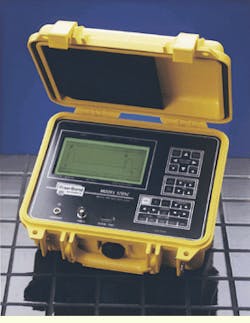
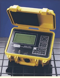
Designed for coaxial and twisted-pair cables, Model 1205C metallic time-domain reflectometer stores on- and off-screen cable data.


