There are three laws of networks. 1) Networks never get slower. 2) Networks never get smaller. 3) Networks never stay the same. Network end users and system designers are constantly planning for higher speeds, more traffic and capacity, as well as flexibility and reconfiguration for manageability.
Fiber-based LANs are all about speed and capacity. The need for bandwidth continues to be driven by information-rich, delay-sensitive applications that demand ever-increasing network speeds.
"Networking" used to mean a few computers sharing a printer, common files, or an Internet connection. These devices were interconnected with horizontal structured copper cabling. Highly complex LANs now consist of an office full of computers sharing multiple common resources. Complexity grows as multiple LANs are networked into campus, metropolitan, and wide area networks. The backbone cables that link LANs together must have an order-of-magnitude greater bandwidth capacity than that of the LANs they support. Today, the drivers are Gigabit Ethernet, Ethernet in the First Mile, and even the on-the-horizon 40-Gigabit Ethernet.
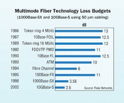
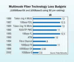
LANs differ from their long-haul wide area cousins. Multimode fiber dominates in premises networks, where link lengths are relatively short with few or no splices. Optical-loss events are closely spaced and the number of terminated links that must be tested is large. It is not unusual for the number of links to exceed 1,000, especially when fiber is installed in the horizontal. As a result of the need for links with gigabit or even faster speeds, attenuation budgets have decreased significantly.
Evolution, not revolution
We have come a long way since 1986, when the data rate for networking was around 4 Mbits/sec with token ring. Rapid technology growth has taken the data rates up to 10 Gbits/sec with networking systems like 10GBase-S, and predictions have speeds rising to 40 Gbits/sec in the future.
null
Traditional premises cabling design includes an optical-fiber backbone and UTP Category 5e or 6 cabling to the desktop. But technology, changes in architecture, and new applications are pushing bandwidth closer to the desktop via fiber. Beneficial characteristics unique to fiber, such as immunity to EMI and other interference sources, support this migration of fiber closer to the desktop. Fiber loss budgets, however, are significantly tighter than they were before the development of gigabit-speed technology, as higher speeds over shorter distances become more prevalent.
Recently, the IEEE 802.3ae produced the 10-Gigabit Ethernet standard, which is an optical-media-only technology. Based on that IEEE standard, the TIA Fiber Optics Engineering Committee, FO-4, wrote TIA/EIA-492AAAC—a detailed specification for graded-index 50/125-µm multimode fiber that enables users and cable manufacturers to specify high-bandwidth laser-optimized fiber at 850 nanometers (nm). Yet another new addendum, TIA/EIA-568B.3-1 supports the transmission of 10 Gbits/sec data rates up to 300 meters using this standardized fiber.
The new addendum was developed in conjunction with the emerging 10-Gbit/sec applications in Ethernet and Fibre Channel, so that this fiber could support these applications in commercial buildings. Because this laser-optimized fiber also supports the premises applications available today, such as FDDI, 100-Mbit/sec Ethernet, and Gigabit Ethernet, it is a natural extension of the recognized fiber types in TIA/EIA-568B.3 and TIA/EIA-568B.1. To sufficiently install this fiber, you must also test and certify it to the documented standards.
Varying testing standards
With the approval of the new fiber addendum and with the results from the most recent BICSI survey, a TR-42.8 task group emerged to establish a scope and create a document to clarify and explain proper test procedures. Currently in approval stages is the TIA/EIA Telecommunications Systems Bulletin TSB-140, which will describe field-testing of length, optical loss, and polarity in optical fiber cabling using an optical loss test set (OLTS), optical time-domain reflectometer (OTDR), and a visual fault locator (VFL). The purpose of the TSB is to clarify the testing of installed premises fiber as it relates to ensuring overall network integrity, reliability, and performance.
This document will not replace the current standards, TIA/EIA-526-7 (for singlemode) and TIA/EIA-526-14 (for multimode), which were first written almost 20 years ago. Rather, the TSB will enhance knowledge of these testing procedures and their use. The standards committee wants to clarify the tests needed to specify the best methods to be used in premises networks to address evolving applications.
TIA/EIA-526-14A specifies three test methods for testing multimode optical fiber networks using an OLTS. Method A tests the multimode cable and has traditionally been used in outside plant, but does not take into consideration all the connections within the link. Method B tests the cable in buildings and the connections at each end, and is specified in TIA/EIA-568B.1. Method C provides the user with channel testing, which is not realistic, as patch cords usually are not left at the end of the fiber cable, either in the telecommunications room or at the outlet. The test results for each of the test methods will differ for a cabling segment.
TSB-140 will clarify which test method to use, because it offers two tiers of testing from which the designer can choose to specify, depending on the installation and requirements of the end user. In addition to allowing specifying two tiers of testing, TSB-140 will describe the functional use of the different tools—OLTS, VFL, and OTDR—and test methods, fiber sources and test jumpers, as well as proper documentation that will complete the cable-plant certification. Although the various test requirements can be contained in separate instruments, the TSB recognizes that they may be included in one instrument, which will likely save significant time and cost.
null
The Tier 1 specification of TSB-140 clarifies loss testing by using Method B of TIA/EIA-526-14A, which most closely emulates what the system will "see" on the fiber. In addition to loss testing, Tier 1 also specifies verifying the cabling length (which may be by use of an OLTS) and polarity verification by use of the OLTS or a VFL.
Tier 2 includes tests described for Tier 1 plus the addition of OTDR testing. Tier 2 involves testing the installed cabling for irregularities, such as a severe bend in the cable, and assuring uniformity of cable attenuation and connector insertion loss. Testing is specified to provide quantitative measurements of the installed condition and overall performance of the entire cabling system and its components.
Hierarchy of testing tools
A VFL can be used to verify polarity and can also be used to detect bends or breaks in the cable. Basically, a VFL is a high-powered infrared laser that streams light into one end of the cable. In doing so, the VFL identifies the continuity and identifies the connectors in the patch panels or outlets, should they be transposed.
An OLTS incorporates two components—a light source and an optical power meter. The basic OLTS is a meter and a source contained in separate units that test one fiber at a time. Using this tool, one person would have to manually calculate the reference measurement with the test measurement after writing them down, and compare the results to the standards. The second type of OLTS automatically makes the calculation with the reference measurement and the test measurement.
The third type of test tool, an advanced OLTS, is also known as a certifying test set (CTS). The CTS can set the reference measurement, measure and calculate the loss and length of the cabling while comparing them to a standards library, verify polarity, and save all the information to be uploaded to a PC for analysis and report generation. A CTS includes a main and remote unit, one for each end of the link under test. Each unit houses a power meter and a dual-wavelength source. A CTS also incorporates loss testing, length measurement, pass/fail analysis and data logging in a single pair of instruments.
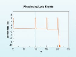
An OTDR is an advanced optical-fiber certification and diagnostic tool that is used to characterize power loss by sending short pulses of light from one end of a fiber, then analyzing the backscattered light from the fiber. Light backscattered from the fiber travels back to the OTDR, where its optical power and arrival time are recorded and graphically displayed as what is called a "trace." The OTDR has the capability to measure the length of the fiber and determine the power loss between any two points along the fiber.
The OTDR enables measurement of elements along a fiber link, including the segment length, attenuation uniformity and rate, connector location and loss, and other power-loss events such as a sharp bend. You can visually locate reflective events (connections, fiber breaks) and non-reflective events (splices, tight bends) by analyzing the graphical trace or by using an event table that may be generated by the OTDR.
In the Tier 2 specification of TSB-140, a more-thorough analysis of the link under test is achieved by using an OTDR. In premises networks, OTDR measurements are particularly effective because splices are rare in these types of networks, and each connection should be consistent. Since 85% of failures can be attributed to bad connectors, results from an OTDR become critical.
Integrated solution
A high-end OLTS and the OTDR are complementary in testing optical-fiber premises networks, and capabilities from both tools should be used for certifying fiber cable installations. Certification of the cabling will produce reports directly from the test instrument, or the data can be downloaded to a computer. Whereas the OLTS will most closely emulate the system to be tested, the OTDR works indirectly to characterize the installed cabling channel. Combining the best capabilities of both testers will become crucial for designers, installers and, ultimately, the end user.
System designers and end users want to see detailed reports of their fiber network, in addition to pass/fail reports. In reality, however, the installer will want to limit the amount of equipment to be carried to the jobsite. "More and more high-speed fiber installations are requiring certification beyond mere loss and length testing before turning over the cable plant," says Marco Mercado, fiber optics manager for Compel (www.compel.com), a technology service provider in Phoenix, AZ. "We are finding that we need to measure insertion loss and deliver an OTDR trace to provide a complete picture of the network."
Fluke Networks of Everett, WA (www.flukenetworks.com) recently ad- dressed concerns of installers like Compel's Mercado when it introduced a generation of optical-fiber field-test instruments that combine an OLTS and an OTDR to certify, troubleshoot, and document the fiber network. With this single tool, called OptiFiber, users can address the specifications in Tier 2 of TSB-140.
The final step to turning over any cable plant to the end user is sufficient test-result documentation that has been recorded through the tester and downloaded to a PC. According to the requirements of TSB-140, test results should include the date, equipment, description, date of calibration, trace of the fiber or cabling link, test wavelengths, and fiber identification or circuit identifier with fiber length and attenuation of events.
The soon-to-be-ratified TSB-140 will change the way system designers specify testing procedures. By incorporating the proposed two-tier testing method and more graphical traces, installers have the most complete picture of the fiber installation, while network owners have proof of a quality installation.
Robert Jensen, RCDD, is fiber optics programs manager of Fluke Networks (www.flukenetworks.com). He also chairs the TIA TR-42 Engineering Committee and TR-42.8 Optical Fiber Test Certification Task Group, is editor of the TIA/EIA-568B.1 standard and BICSI's principle member of NFPA Panel 16.


