Cabling professionals must be prepared to positively interact with other construction trades.
For months, we in the communications-cabling industry have been hearing about Division 17 and how it will change our professional world. In fact, the efforts to add a 17th division to the MasterFormat of the Construction Specifications Institute (CSI) are years, not months, old. Trade publications like this one and others have tracked the efforts of Division 17 advocates for some time, but the prospect of Division 17 is getting closer by the day.
Assuming that Division 17, as proposed by interested communications-cabling professionals, is in fact incorporated into the MasterFormat (and that is an assumption), we probably are not more than 18 months away from that incorporation. For several months now, we have been hearing that our world will change as a result. We have been hearing that our work of designing, specifying, recommending, and installing communications networks is not going to be the same anymore. And that talk of change is not just idle gossip. Division 17, if implemented as proposed, will change everything for us.
Essentially, Division 17 will recognize communications-cabling infrastructure as a building system, the same way that plumbing, heating/ventilating, and electrical systems are considered building systems. And the professionals who design and install these building systems have specific responsibilities with respect to the overall construction project. Therefore, you-as a communications-cabling-system professional-will have responsibilities with respect to the overall construction project.
For years, the design and construction of low-voltage networks in new-construction projects has been sort of like the tail wagging the dog. We usually are brought into a construction project rather late-well after drawings are underway or even completed, and too late for us to head off what frequently amount to costly change orders and project delays that result from us not being part of that process. And that is the crux of the issue: we are not part of the process.
What Division 17 will mean
In short, Division 17 will integrate the communications-system design element into the construction industry. It will propel us all into a different way of doing business. The impending change will have little to do with your technical abilities, your understanding of how to properly specify and install communications systems, or the value you bring to architects and general contractors in terms of your specialized knowledge of network products and installation methods. The change will have everything to do with how you work, because Division 17 will bring us all directly into the fold of how buildings are renovated and built.
In the world of Division 17, your technical knowledge won't be enough. You are going to need computer-aided design (CAD) drawing skills; you are going to need to know how to read blueprints and decipher annotations primarily intended for other trades, such as electricians, painters, and concrete workers.
Admittedly, change can be tough and difficult to handle. But from my perspective, the changes from Division 17 with which we all will have to contend will be entirely good news for us. Essentially, Division 17 will place us on equal footing with other building systems in a construction project. That means we will be involved from the beginning of a project.
The changes we face are not as daunting as they may seem initially, because we are not alone. We are not forced to reinvent the wheel because we have the opportunity to learn from a vast, established, existing body of knowledge and people-people with whom we will be working closely. In addition to working with new people, expect to have to learn some new skills, as well as the language that will allow you to communicate effectively with others on a construction project, and several processes that you likely have not been part of in the past.
This article will address terms and practices that are basics for the construction industry. It assumes that you have worked outside the mainstream construction process-as many in the cabling industry have-and will benefit from a nuts-and-bolts presentation of these concepts.
Phases of construction projects
Construction projects include three phases: design, bidding, and construction. In the design phase, the first steps are analysis and planning. At this high-level stage, the work includes determining how the building will be used and setting a budget for the project. From this feasibility analysis, actual designs must be prepared for the owner by the architectural firm. The architectural firm's designs present an increasingly detailed view of the building or campus, beginning with the general and moving to the specific. An initial schematic design is made up mostly of sketches with general design criteria; it includes rough cost estimates.
Why would you want to be involved this early in the process? For one thing, you might be able to point out that placement of a parking lot or indoor water garden will require additional work for pathways between and within buildings. And your input, even this early, helps the team form a more accurate preliminary cost estimate.
Once the high-level schematic design is approved, the design team begins the detailed design development. This phase usually includes formal reviews by the building owner at the 50% and 80% marks to review specifications, drawings, and estimates. Here is where you play a major role.
Once the design development phase is complete, formal construction documents are prepared, which are used to obtain pricing for each element of the project. They include instructions to bidders, bid forms, contract forms, and the project's general conditions.
Once the contractors are selected and the project is ready to commence, the construction phase begins. Here, agreements between the owner and contractors are executed. Throughout the construction phase, such documents as shop drawings, modifications, and record documents are produced. The end of this phase includes the preparation of punch lists and completion surveys.
Cutover signals the post-construction phase, which includes such activities as training the owner's personnel and warranty inspections. As-built versions of the drawings are produced and incorporated into a computer-aided facility-management system.
Roles and expectations
With that quick overview, let's examine some specifics. First, what are the team members' roles and expectations in the design phase? It's here that the owner, architect, engineer, and consultants are most active.
The owner defines the requirements and approvals to ensure the project stays on track. That may sound unusual to you, particularly if you believe that the building owner does not know much about what is needed from the communications system. But under Division 17, the owner will set requirements.
The architect takes the lead selecting the design team, putting together the aforementioned schedules, and coordinating the architectural consultants and owner consultants. Cabling professionals frequently become part of the mix in this coordination effort. We are hired by the owner, not by the architect. And for many of us, the biggest difference will be that we actually are included in this stage of the project.
The engineer is a state-licensed design professional who focuses on specific systems or requirements. A project frequently has several engineers, including structural, mechanical, and electrical. They prepare drawings, specifications, and estimates based on the architect's scope and timelines.
Consultants are design professionals who focus on specific requirements, such as telecommunications. As previously mentioned, some consultants work for the building owner while some work for the architect.
Not what you expect
The expectations for you as a cabling designer or installer during this design phase may differ significantly from that with which you are accustomed. If you are used to hearing requests like, "Just give me a ballpark figure," then perhaps you should use an audio recorder to capture those requests now. Because with Division 17 in effect, you will not hear anything like that again. Demands will be specific, and your responses will have to be precise.
Design drawings
The owner's expectations of the drawings in the design phase incorporate the 4 C's: clear, concise, complete, and correct. The drawings provide instructions for the building; they are not just outlines of buildings and walls. They include symbols and line styles that provide important information for the project. In fact, they are the basis for all other activities on the project. Within these drawings, every element of the telecommunications system-including how it relates to and supports all other building systems-is known and documented.
Drawings present not only an opportunity for learning, but also a requirement for it. Drawings for the entire building, including all systems, are done using a CAD package. CAD enables clear communications between engineers and trades, and each trade has become skilled at reading these drawings. For our business, CAD is a must. And it is a potential time-saver. Consider the value of using existing CAD drawings of floors, rooms, and furnishings as your basis for drawing a communications network. A lot of your work is already done.
Drawings are grouped by discipline and designated by letters, as follows: civil (C), structural (S), architectural (A), mechanical (M), electrical (E), plumbing (P), telecommunications (T), fire protection (F). These groups work together, and each holds equal importance.
In addition to those groups, drawings are separated into types, including: plan, elevation, section, detail, schedule, and general.
- A plan shows horizontal views; an example of one is a floor plan.
- Elevation drawings provide vertical views, such as that of a wall or rack.
- Section drawings provide sectional views. A section drawing is where you would find a sleeve through a wall.
- Items like faceplate labeling appear on detail drawings.
- Tables of information or spreadsheets in schedule drawings will have items like the crossconnect schedule.
- The general drawings provide symbols, legends, and notes.
Why do you have to know all this? As designers and consultants, you will probably be brought into projects earlier than you have in the past. So, you have to be able to read and understand the working plans of other trades to make sure the communications infrastructure is designed in sync with other building systems. To fulfill the obligations of your job, you need to know plans for rooftops, entrance facilities, riser systems, building automation, and many others. In essence, drawings are the common language for construction projects. It is imperative that you know the language.
T drawings detailed
The six T series drawings (T0 to T5) defined in the Division 17 draft will become a crucial part of the construction documents. These will be done in AutoCAD, which lets you layer drawings, letting you turn on or off certain design elements. This ability is important not just in designing, but also for contractors during installation. With layers, you will be able to clearly see important building elements that impact your drawing of the communications network.
For example, in the A drawings, you are probably interested in seeing layers that include the ceiling, roof, and room numbers. And even in your own T drawings, it is helpful to be able to layer and isolate each design element. Examples include aerial fiber, blank and existing drops, and sound systems.
Here is an explanation of the different levels of T drawings:
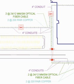
- T0-Campus or site view. Shows physical and logical connections for a campus or site plan view. It shows actual buildings, major system nodes, interbuilding backbones, and exterior pathways. The T0 drawings have 16 unique drawing requirements for such elements as site plan, riser drawings, and pathways. Each drawing goes by a unique abbreviation.
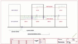
- T1-Floor layouts. Shows the layout of a complete building for each floor, revealing horizontal pathways, backbone systems, location of serving zones, access points, and other systems. The A drawing typically serves as the basis for T1 drawings. In these drawings, you likely will find backbone logical drawings for copper and optical fiber
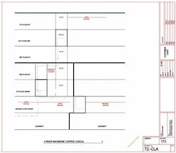
- T2-Serving zones. Shows serving zones; e.g. drop locations, telecommunications equipment rooms, access points, and cable identifiers. At this level, you will find substantial numbers of symbols and codes describing the facility. For example, symbols are used to designate drop locations, drop locations to be rewired, drop locations with blank plates, ceiling-mounted phone locations, and horizontal fiber to the desktop. T2 drawings also use abbreviations like FW for fishable wall, SC for surface-box-to-ceiling, CC for conduit-to-ceiling, and RC for raceway-to-hallway.
- T3-Equipment rooms. Shows the layout for such items as racks, ladder racks, and patch panels. These drawings also show architectural, mechanical, electrical, and plumbing elevations as well as rack and backboard elevations. Once again, symbols prove extremely helpful nomenclature here.
- T4-Details. Shows faceplate labeling, faceplate types, installation procedures, detail racking, firestopping, raceways, and other project details.
- T5-Schedules. Covers all miscellaneous requirements of the communications system. Schedules, plans, and unique instructions are included here. As an example, spreadsheets that are considered T5 drawings may show information for cutovers and plant management.
Specifications and cost estimates
Next in the design phase come specifications, which are used to define project requirements. There are four types of specifications: performance, proprietary, descriptive, and reference.
- Performance specifications focus on results. They allow contractors to choose materials and installation methods.
- Proprietary specifications call out brand names and models.
- Descriptive specifications focus on exact properties and installation methods.
- Reference specifications are based on established standards.
For specifications, the construction industry long has enjoyed a standard format for construction documents. The MasterFormat, produced by CSI and Construction Specifications Canada, organizes the activities and requirements of a construction project into front-end sections as well as 16 divisions. Examples are metals, doors and windows, furnishings, mechanical, and electrical. The proposed Division 17 is designed to organize telecommunications requirements within a building. Specifications for telecommunications, and all existing divisions, are standardized. Each section is divided into three parts: General, Product, and Execution.
Once specifications are complete, the third component of the design phase is the preparation of cost estimates for the architect and owner. Cost estimates are significantly more complicated than the sum of parts and labor. The estimates account for general conditions, such as insurance, advertising for bidding, and bonding. They incorporate design and project-management costs, including fees for architects, engineers, and consultants. The estimates also consider market conditions, such as seasonal effects on labor, and existing conditions, such as soil conditions and the presence of hazardous materials.
Let the bidding begin
With the bulk of the building design set in stone and the specifications complete, the bidding phase begins. Again, it is crucial to consider the roles and expectations of the parties involved. The owner provides bidding and contracting requirements and has final say on selection of contractors and subcontractors. Architects, engineers, and consultants may participate in bid evaluation and negotiation, and present alternates and substitutions to the owner. In this phase, a new face enters-the construction manager. The construction manager may actually lead the bidding process and play a key role in the evaluation of bids. The general contractor prepares a bid that includes subcontractor bids. Just as in the design phase, during bidding the expectations boil down to clear, concise, complete, and correct drawings and specifications.
Chances are excellent that you will have more knowledge of communications issues than anyone else on the team. But if you are not part of the project until after drawings are completed and bids are negotiated, then you have missed the opportunity to advise and guide, as appropriate, on the project.
The bid itself typically contains: instructions to bidders; reference items such as existing conditions and a description of the site and buildings; bid-response forms and contract forms; specifications in the MasterFormat Divisions; and drawings.
Construction phase
For as much as this article has focused on getting involved in construction projects, so far, there has been little discussion of actual "construction." But once the contractors-including subcontractors-are selected, the construction phase begins. The members of the team remain the same, but their functions and focuses change.
The owner's new function is to make payments. Architects, engineers, and consultants now conduct inspections, ensure that work is in compliance with specifications, and make modifications as needed. The construction manager is responsible for the construction site, and may issue change orders. And depending on the size of the project, the general contractor may also serve the construction manager role.
The owner, however, does not just pay bills during the construction phase. The owner can stop work, complete work the contractor fails to finish, or even partially occupy the building. Most importantly, the owner can terminate the contract during this phase.
The construction phase also incorporates terms, forms, and procedures that will be new to you if you have not previously been involved up-front in these types of projects. From different contract types (like stipulated sum, cost-plus-fee, and unit price) to forms (such as notice to proceed, field orders, change orders, and punch lists), and submittals other than those with which we already are familiar, it is absolutely critical that you integrate effectively with other trades.
Remember that how a building is built today ultimately determines how much it costs over its lifetime. There are many benefits to getting involved early, during planning and design. For example, many spreadsheets are not necessarily set up for use by telecommunications trades. They typically show schedules for door and carpeting installation, as well as painting. But seeing these schedules early enough gives you more information for preliminary estimates. And you will have the ability to show the client options.
Being a member of the design team gives you the chance to add value and elevate your capabilities. You can provide your schedules early in the process, like those for PC moves, crossconnection, telephone-set placement, and faceplate installation.
Frequently, many special requirements for the entire project reside in other divisions. For example, it may be stipulated that work can only be done between midnight and 8 a.m. When you know this fact up-front, you can prepare for it.
In short, early involvement gives you knowledge. And knowledge elevates your position in the project. Above all, remember that the change we are facing with Division 17 is a good change, but one that will take effort from all elements. Education within the telecommunications and construction industries is essential.
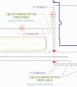
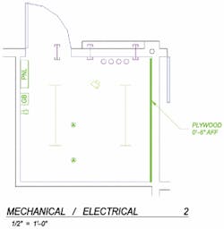
Editor's note: This article is based on a presentation entitled "The language, people, and processes of construction projects," which Mr. Feaster gave at BICSI's Spring 2001 Conference, held in May. The drawings in this article are actual drawing from BICSI's headquarters expansion project. They were drawn in the proposed Division 17 format.
Al Feaster, RCDD, is program manager, Broadband Infrastructure & Access Group, ADC.
