Centralized fiber optics and a fiber/Category 5 design give the agency much-needed flexibility.
Preston Buck
Corning Inc.
In May 1996, NASA`s Goddard Space Flight Center (GSFC--Greenbelt, MD) began a three-year overhaul of its extensive communications infrastructure. A major part of this work involved replacing coaxial Ethernet cables in the flight-center buildings--60 spread over 1121 acres--with fiber-optic and Category 5 unshielded twisted-pair (UTP) copper cables as well as installing new interbuilding fiber-optic cable. The fiber-optic backbone and Category 5 structured cable to the desktop in each building provide network connectivity to all flight-center users at data rates in excess of 155 megabits per second.
In addition, the flight center recently added a major building to its campus: the Earth Systems Science Building (ESSB), home to 820 employees of Goddard`s Earth Science Directorate. The central structure of the ESSB is a curved spine from which extend four wings, like the fingers of a hand. Each wing has four floors; the spine consists of four floors and a subgrade service level. As with any large building, this one presented a number of network cabling challenges.
Network planners--engineers in the flight center`s Center Network Environment working with Siemens Information and Communication Networks Inc. (Siemens ICN--Boca Raton, FL)--designed the ESSB network to provide high-speed connections between wiring closets throughout the building because the network would have to support Ethernet, Fast Ethernet, Asynchronous Transfer Mode, and Fiber Distributed Data Interface (FDDI). However, planners knew that in the future, the network would require more bandwidth than Category 5 could deliver to desktops. Also, they had made a substantial investment in fiber network interface cards (NICs) for computers to be moved into the new building.
Therefore, planners decided to go with a dual-network solution, with two cabling infrastructures:
As with other buildings on the flight-center campus, an optical-fiber/Category 5 infrastructure provides baseline 10-Mbit/sec shared Ethernet connectivity to support typical administrative network requirements. At ESSB, fiber-optic backbone cables travel from the main crossconnect (MC), on the service level, to telecommunications closets (TCs), and Category 5 cables connect closets and desktops in a star configuration. TCs are positioned at the building`s wing-spine junctures, one per wing per floor, for a total of 16 closets.
To support FDDI and future bandwidth requirements, a centralized fiber-optic network provides fiber homerun connections from the MC to more than 1100 desktops.
The prime contractor for the installation was Siemens ICN, which was responsible for all final physical-plant design, purchasing and inventory of all materials, computer-aided design drawings, and labeling and certification documentation. Siemens ICN business partner Telstar Communications (Muncie, IN), a member of Siecor`s LANscape Extended Warranty Program, performed the installation of equipment racks, ladder rack cable support, fiber distribution cabinets (FDCs), patch panels, and cable-management panels, as well as the installation, termination, and testing of cables. All cabling was provided by Siecor; optical fiber was manufactured by Corning Inc.
Because the fiber-optic installation was so massive, the installation required cable management that should be instructive to installers. Also, the unusual dual-cabling design at ESSB offers a unique opportunity to compare distributed and centralized cabling networks in a single setting.
Centralized vs. distributed design
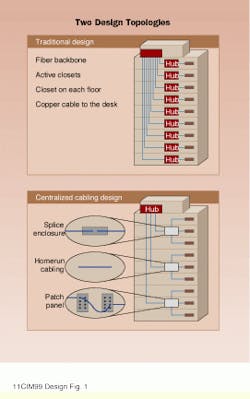
The fiber-optic centralized network design, which is becoming increasingly popular, provides direct connections between hundreds, even thousands of workstations and a single MC by using pull-through fiber-optic cables or a splice or interconnect in the TC. All data electronics are housed in a single location. With direct connections between network hardware and desktops, maintenance and troubleshooting are vastly simplified.
Contrast that with the conventional, distributed network design, where active electronics--hubs, concentrators, and switches--are housed in TCs distributed throughout a building, within 300 feet of users. Backbone cables travel from an MC (or, in an interbuilding network, an intermediate crossconnect) to one or more horizontal crossconnects within TCs on each floor of a building. Individual outlets for each user are located within 100 meters of the TC and connected to the horizontal crossconnect using a single cable per user in a physical star configuration.
In the conventional design, interbuilding and intrabuilding backbone cable is optical fiber; the horizontal segment of the network typically consists of unshielded twisted-pair (UTP) copper cable. The transmission distance limitations inherent in copper cabling make the distributed design a necessity because using copper in the horizontal requires that data electronics be located no more than 100 meters from workstations.
The ESSB network
The MC of the ESSB network consists of 14 racks on the service level. Here are terminated the preconnectorized Siecor fiber-optic backbone cables, comprising 48 Corning 62.5/125-micron multimode fibers and 24 Corning singlemode fibers, which run to the 16 TCs; and the Siecor 2-fiber cables that run directly to nearly every workstation throughout the building. Also housed within the MC are cabling termination points for telephone and video service.
Distributed fiber/copper network
Fiber-optic backbone cables travel from the MC to a centrally located riser shaft and then to the first floor of the ESSB. From this point, backbone cables for all floors in each wing run to the four first-floor TCs. Fiber backbone cables for the second, third, and fourth floors rise directly upward from each first-floor closet. Fibers are terminated at each closet`s FDC; from there, Category 5 copper cables complete the trip to work-area outlets.
Fiber-optic centralized network
The centralized fiber-to-the-desk design is simple: 2-fiber cables travel directly from the racks in the MC to work-area outlets throughout the ESSB. Bundled by floor and wing, cables run from the racks to the central riser shaft, up to the correct floor, along ceiling ladder racks to the appropriate wing, and on to drops at each work-area outlet.
The centralized fiber-optic design offers many benefits, including improved security, fewer points of failure, and reduced TC build-out costs. Consolidating network electronics, analyzers, uninterruptible power supplies, crossconnects, and servers at a single location greatly simplifies local-area-network (LAN) management, provides more efficient use of hubs, and allows for simple implementation of various network applications. Perhaps most significantly, the centralized fiber-optic cabling design provides a cost-effective alternative to the traditional design, because using fewer active components streamlines installation, simplifies maintenance, and lowers overall costs.
"The centralized fiber homerun setup means fewer closets to set up and build and fewer cables to terminate, test, and troubleshoot," says Quentin Foister, network installation project manager at Telstar Communications. "With the distributed design, there are considerably more terminations and chances for problems. Also, this design reduces the amount of signal loss due to fewer connections over the fiber transmission media."
In fact, in-house network planners and Siemens considered three basic design architectures for their fiber-to-the-desk network:
* separate homeruns to desktops from the 16 TCs
* homeruns from a centralized closet on each floor, with backbone cables to the MC
* the centralized design directly linking the MC and desktops.
The final option, which they chose, was the least expensive, taking into account termination costs, patch cables, and network management. Also, the centralized design "was most desirable because of flexibility," recalls Gene Gottschalk, chief systems engineer, Raytheon ITSS, who worked on the original network design. "We could do all the crossconnects from one location. The more you can consolidate your work into one location, the more efficient you can become during installation because you`re not running all over the building."
Moreover, this fiber-optic centralized design reduces costs through improved port and chassis utilization. Centralizing all electronics in the MC reduces the number of ports and chassis required by a network, resulting in cost savings. On average, only 70% of hub ports are used in the conventional decentralized design, due to the varying number of users per TC. The centralized design is much more efficient--typically hub port usage is 90%. That 20% differential results in immediate savings.
Challenges and solutions
The many benefits of the fiber-optic centralized design notwithstanding, at ESSB the hundreds of cables and the long distances involved--the longest cable is approximately 650 feet--presented a challenge to installers.
"The difficulty in this setup," says Foister, "is the length of the cables--that is, running the cables down to the service level where the MC is located. Thankfully, there was a dedicated riser shaft with a large cable-tray system down to the basement. The other difficulty was dressing all those cables in an organized and neat way."
Installers first pulled fiber cables from the riser shaft on each floor to the work-area outlets. Next, they measured the distance from the riser closet to the appropriate rack in the MC plus some slack, cut the cable, and dropped it down the riser shaft to the service level. At each level, a support system of conduit brings the fiber cable from horizontal to vertical before its descent within the riser shaft.
Of course, this large number of cables traveling down from each of four floors to the basement constitutes a tremendous amount of weight. To relieve the stress, bundles of cable were tie-wrapped to every cross-member of the ladder rack within the riser shaft. Starting at the bottom, installers used a split column grip to hoist the cables upward slightly before tie-wrapping to cross-members. Each wrap is snug but not tight.
"The tie-wraps are not tight at all," says Lewis (Chip) Palumbo, registered communications distribution designer (RCDD) and site project manager with Siemens ICN. "Because there are so many of them, the tie-wraps don`t have to be tight. You can move them easily with your fingers."
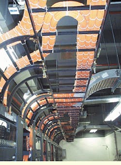
At the service level, bundles of fiber-optic cable move through conduit placed in the wall and into the room housing the MC. Cables travel along horizontal ladder racks to their destinations in the FDCs. Service loops are left in the fiber on these racks so that any fiber can be moved and reconnected on a different FDC if necessary.
Meticulous preparation was key to the successful installation. "When you`re doing long homeruns, planning is complex," says Patrick Barron, RCDD, of Telstar Communications. "The critical things are planning, labeling, and having enough people."
The centralized design, according to Barron, did simplify the installation: "Having fiber terminations in one place makes things easier. And thanks to careful planning, very few cables had to be re-pulled."
The completed cabling infrastructure provides ESSB network managers with flexibility for the present and capacity for future bandwidth demands. The fiber-optic centralized network simplifies network design and maintenance by eliminating horizontal crossconnects throughout the large building; reduces costs by requiring fewer active components and closets; and with homerun cables between the MC and all work areas, greatly simplifies termination, testing, and troubleshooting.
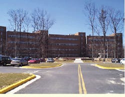
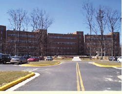
The Earth Systems Science Building, on the campus of the NASA Goddard Space Flight Center, in Greenbelt, MD, is home to Goddard`s Earth Science Directorate.
In the traditional cabling design (top), cables run to hubs in telecommunications closets located within 300 feet of users. Category 5 copper cables connect closets to users. In the centralized fiber-optic cabling design (bottom), fiber-to-the-desk is achieved with direct connections between a single hub and each user. All data electronics are housed in one location.
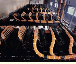
From these racks located on the Earth Systems Science Building service level, more than 1100 2-fiber cables are homerun to work-area outlets throughout the building.
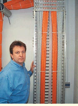
In the riser closet on the first floor, Chip Palumbo, site project manager with Siemens ICN, stands beside backbone cables for telephone (left and right sides), distributed network (orange fiber cables), and video (center). Fiber homerun cables for the first floor are visible at left and above.
Sweeping service loops were left in the cables to allow for moves among the fiber distribution cabinets (bottom).
Preston Buck is market manager of premises at Corning Inc. (Corning, NY). The author acknowledges the contribution of Scott Andrus, federal government account manager at Siecor (Hickory, NC), to this article.
