Transmission requirements for GbE over copper have given rise to a new set of transmission performance parameters.
Hugo Draye
Fluke Corp.
Field-testing a structured cabling system provides the assurance that a completed installation meets the desired transmission performance. A prerequisite to testing, therefore, is that the desired performance be agreed upon by all parties involved.
In the United States, the Telecommunications Industry Association (TIA--Arlington, VA) has been the leading industry organization to develop and publish standards documents for data- and voice-communications infrastructure. Standards such as TIA/EIA-568a define performance specifications for both twisted-pair cable and connecting hardware. The performance of an installed cabling link is a function of the quality and capability of the components--both cable and connecting hardware. Performance is also a function of the workmanship and care with which the installation is executed.
TIA telecommunications systems bulletin TSB-67, published in October 1995, defines the transmission performance of the installed link that is designed in accordance with TIA/EIA-568a guidelines. TSB-67 remains the only official standards document that specifies the guidelines for field-testing the installed link. This document defines two models for the installed link: channel and basic link. Furthermore, it defines
* parameters that need to be measured and verified
* the frequency range over which the evaluation needs to be executed
* performance or pass/fail limits for this evaluation.
Framework for performance analysis
A communications system consists of a transmitter that sends signals via a transmission medium to a receiver. For the purpose of this article, the transmission medium is a twisted-pair cabling link.
Such links use two wire pairs to communicate in both directions. Each pair is used in half-duplex mode. The standard data cable contains four wire-pairs, but legacy networks have typically used just two of the four pairs.
The goal of field-testing is to verify the installed link will transmit signals with a high degree of integrity to ensure reliable communications. Performance analysis is based on an evaluation of the signal-to-noise ratio (SNR) of the transmission link over the frequency range required by the application. The SNR expresses the strength of the desired signal--the signal to be received from the sender--relative to external disturbances such as noise that find their way onto the transmission link. As long as the desired signal is sufficiently strong relative to the combined effect of unwanted disturbances, the receiver will have little or no problem in decoding the desired signal. Communication takes place with a very low bit-error rate and all is well.
The strength of the signal at the receiver end is measured by the attenuation parameter. Furthermore, different sources of noise must be identified and their influence measured to ensure they remain sufficiently small to maintain a favorable SNR.
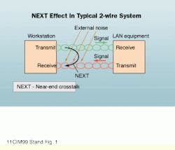
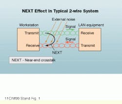
TSB-67 requires four measurements or performance criteria: wire map, length, attenuation, and near-end crosstalk (NEXT). In addition, the standards have defined acceptance criteria for propagation and delay skew that are included in the autotest mode of most field testers.
Bandwidth is derived form the measurements defined above. Ideally, the signal transmitted from the hub should be the same strength when it is received at the workstation. But because signals are subject to attenuation, as signal frequency increases, loss due to attenuation increases. As a result, the signal gets weaker by the time it reaches the receiver. As signal frequency increases, NEXT coupling becomes stronger until a frequency is reached where the attenuated signal at the receiver input is about as strong as the noise caused by NEXT coupling. At this frequency, the SNR at the input of the receiver reaches the value of "1." The noise is as strong as the signal we are trying to detect and decode. The receiver can no longer distinguish the noise from the desired signal, and the transmission fails.
Actually, the transmission fails before this critical frequency has been reached. In twisted-pair link testing, this SNR is called attenuation-to-crosstalk ratio (ACR)--a calculated value for each frequency in the test spectrum--and is obtained by subtracting the measured attenuation value at each frequency from the measured NEXT value at the same frequency. Both attenuation and NEXT are measured in decibels (a logarithmic scale), and a ratio is computed as the difference in dB values. ACR equals 0 when the SNR equals 1. ACR equals approximately 10 when the SNR is 3. A link that meets the minimal Category 5 requirements for attenuation and NEXT delivers an ACR value of 3.5 dB at 100 megahertz.
If a cabling link passes test requirements for both attenuation and NEXT, it also passes the requirement for ACR that is derived from the measurements of these two parameters.
New transmission model
Gigabit Ethernet (GbE) over copper will change the basic 2-wire-pair transmission scheme because it simultaneously transmits signals on all four pairs in full-duplex mode. Each wire-pair in a twisted-pair link carries part of the message, but each pair also transmits data in both directions simultaneously. This model differs significantly from the 2-wire-pair model. But the design rules for GbE specify that this application must operate with the attenuation and NEXT performance specifications of Category 5 cabling links.
Because all four wire pairs carry signals simultaneously in both directions, additional sources of crosstalk and disturbance must be considered in determining the SNR, channel capacity, and bandwidth of the link under test. Specifically, we must consider the return loss and equal-level far-end crosstalk (elfext) performance of the link in addition to the Category 5 performance parameters.
Also, the crosstalk disturbance on a wire pair in the link is no longer the result of one other wire pair but is caused by the combined effect of the three other wire pairs in the link, which gives rise to power-sum parameters.
Lastly, because all wire pairs carry signals simultaneously, the signal-propagation time for each of the wire pairs should approximately be the same; delay skew (the difference between the propagation delay values for the wire pairs) is no longer superfluous.
The standards committees are developing a set of new standards to define the performance of high-performance cabling systems.
All of these standards include the parameters defined in the test procedures of Category 5 cabling plus most or all of the following test parameters: next, power-sum next (ps-next), elfext, power-sum elfext (ps-elfext), power-sum acr (PS-ACR), and return loss.
New standards
The first in the series of new developments is TSB-95, which is a guideline or recommendation rather than a standard. TSB-95 provides the recommended list of new test parameters and their performance limits (pass/fail values) to test existing Category 5 cabling links in case these links are expected to transmit GbE traffic. Attenuation and NEXT requirements for GbE are identical to those of Category 5. TSB-95 recommends performance limits for elfext, ps-elfext, and return loss. All these test parameters are to be evaluated from 1 through 100 MHz.
The standard for Enhanced Category 5 (Category 5E) is the second document in the series of new test standards. Category 5E is a new standard that defines a higher level of link performance than is possible with Category 5 components. The frequency range for Category 5E is the same as for Category 5 (1 through 100 MHz). TSB-95 and the new standard for Category 5E are on a parallel development plan. These documents will likely be ratified and published toward year-end and may be ready in time to be included in the TIA/EIA-568b revision.
The last of the new standards currently under development is Category 6. This standard will likely not be completed until late 2000. The specifications for Category 6 installed links--channel, basic, and permanent links--have been defined for some time. The Category 6 channel has been targeted to deliver the same bandwidth according to the ACR model at 200 MHz that the Category 5 installation delivers at 100 MHz. Test specifications for Category 6 require that components and installed links meet the specified test parameter values from 1 through 250 MHz.
Performance parameters for Category 6 link models have remained fairly constant. However, specifications for Category 6 components are still under study. Category 6 installations offered in the marketplace today are proprietary solutions. Connectors from different vendors are most often not electrically compatible and, therefore, incapable of providing Category 6 link performance.
New test parameters
Test parameters found in the draft Category 6 standard include the following:
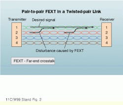
ELFEXT loss--Measures the quality of the signal arriving at the receiver input and considers all of the disturbances that can affect the quality of the signal at the receiver input, including, for example, the interaction between pairs 1 and 2.
Both wire pairs transmit signals from left to right. The signal traveling along pair 2 disturbs the signal on pair 1 as a result of the crosstalk coupling between the two wire pairs. This disturbance generated on wire pair 1 travels in both directions of this wire pair. In this scenario, the crosstalk traveling the same direction as the desired signal (from left to right) causes a disturbance or degradation in signal fidelity and quality at the input of the receiver. This crosstalk disturbance is FEXT.
FEXT--A measure of signal coupling from one wire pair to another pair. Unlike NEXT, the crosstalk signal is measured at the distant end of the link. FEXT is measured by applying a test signal on a wire pair at one end of the link and measuring the disturbance on another wire pair at the other end of the link.
To determine the impact of the FEXT disturbance on the receiver, we must consider the magnitude of the FEXT disturbance relative to the strength or magnitude of the desired signal arriving at the receiver input. The desired signal traveling along wire pair 1 is attenuated along the link. One of the SNRs to be considered expresses the ratio of the FEXT disturbance from wire pair 2 onto wire pair 1 relative to the magnitude of the desired signal arriving at the receiver input of wire pair 1. This ratio, called elfext, is a computed value analogous to the calculation of ACR discussed earlier. elfext loss is critical when two or more wire pairs carry signals in the same direction.
FEXT loss--The ratio of the disturbance measured at the distant end of the link (receiver of pair 1) to the amplitude of the signal that is applied at the local end (transmitter) of a different wire pair (pair 2--the disturbing wire pair).
ELFEXT--The computed ratio of the measured FEXT loss and measured attenuation, or the ratio of the disturbance to the level of the desired signal, which is subject to attenuation. elfext, like ACR, is an indication of SNR.
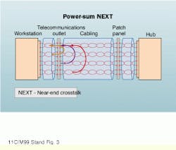
PS-NEXT--Category 5 test procedures require NEXT measurements be tested for each possible wire-pair combination in a twisted-pair cabling link. This process yields test results for six wire-pair combinations performed from both ends of the link under test--a total of 12 sets of test results. When all wire pairs transmit signals concurrently, the disturbance on a receiver input due to crosstalk consists of the combined effect of the other three wire pairs in the cabling link.
The combined effect is defined and computed as the power-sum addition of the pair-to-pair NEXT measurement values. This combined NEXT parameter, therefore, received the name ps-next.
PS-ELFEXT--Similarly, the elfext disturbance on any one wire pair in a link comprises the combined elfext interference caused by the other three wire pairs in the link. This measurement is called ps-elfext. The combined effect is defined and computed as the power-sum addition of the pair-to-pair elfext values.
Return loss--The combined effect of all of the impedance changes along a cabling link, including the source (beginning) and the receiver (end) of the transmission line. A cabling link is a transmission line because the wavelength of the frequencies used on the transmission line is not longer than the length of the link. At any point along the transmission line where a change in impedance occurs, some of the transmitted signal energy is reflected back to the signal source.
Ideally, the construction of twisted-pair cables maintains constant impedance, but in reality, a number of small reflections occur within the cable. These reflections arrive with different time delays at the ends of the link. Cable standards define a parameter called structural return loss (SRL), which expresses the result of this variation in cable impedance. SRL is only applicable to the cable itself.
A cabling link includes both cable and connecting hardware. A connector and the untwisting of wires at a termination introduce an impedance change that is, relatively speaking, much greater than the changes along the cable itself due to SRL. Therefore, reflections occur at the connectors as well. The reflections travel to the ends of the cable and arrive with a phase shift that depends on the distance traveled. The total effect of signal reflections due to these imperfections is captured by the return-loss measurement.
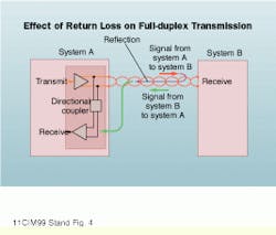
GbE uses every wire pair of a standard 4-wire-pair connection in a full-duplex mode, meaning that inside the network interface devices, the outgoing signal has to be prevented from coupling back into the receiver input. The circuit that provides this function is called a directional coupler. (Your telephone works much the same way: When using a telephone, you can speak and listen to another party.) Echo-cancellation may be used to optimize the performance of the directional coupler.
Signal reflections occur along the link due to imperfections in the link. These reflections travel back to the transmitter. In a system where signals travel simultaneously from system A to system B and system B to system A (full-duplex transmission on each wire pair), reflections created by the signal traveling from A to B cause a disturbance on the signal traveling in the opposite direction. These reflections contribute to the SNR at the receiver input of system A.
The same reasoning applies to the signals traveling in the opposite direction. As a result, to characterize these noise components and verify that they are acceptable, cabling links will have to be tested for return-loss performance in both directions.
Propagation delay and delay skew
Another important parameter when all four wire-pairs are transmitting information concurrently is the difference in propagation time among the wire pairs, which is measured by the parameter called delay skew. The message or information to be transmitted is divided over four paths (wire pairs). Signals should arrive at the receiver in approximately the same order or relation in time as they were launched onto the transmission link to ensure that the complete message is correctly reassembled at the receiver end.
The time for the electrical signal to travel from one end of the link to the other is called the propagation delay of the link. This parameter is typically measured to calculate the length of the wire pairs. Electrical length is based on a time measurement that characterizes the round-trip travel time required by the electrical signals. Since the speed with which electrical signals travel along the cable is known fairly accurately, the distance traveled can easily be calculated as the length of each wire pair. The difference in the propagation delay among the wire pairs yields the delay skew. The difference between the fastest and slowest wire pair must fall within the test pass/fail parameter.
Test parameters for GbE copper-cabling systems have been defined for some time, as have the minimum performance specifications of these parameters for the installed link. These minimum performance specifications serve as the pass/fail limits during field testing of an installation. The standard documents are not yet finished, however, and one or more of these specifications could undergo some changes. Upgrading test-limit values in a field test unit is best accomplished with a software upgrade.
The standards committees are studying the specifications for components--cable and connecting hardware--so that the installed link specification can be achieved with the proper installation of any set of components that meet Category 6 specifications. Standards will not be completed, ratified, and published until these tasks are completed.
In the meantime, many high-performance cabling vendors offer products specified to meet Category 5E or Category 6 performance. The buyer should be aware that the current Category 6 product offerings are proprietary solutions requiring, at a minimum, that all connections be made with components from the same vendor.
To test these high-performance cabling installations, the field-test unit must test and evaluate all of the parameters discussed here over the frequency range of the standard. With the proper equipment, field-testing can be greatly simplified because most test-equipment manufacturers offer an autotest mode in which the tester executes all the measurements required by the selected test standard. It is the duty of the technician to select the proper test standard in the setup of the test equipment. Furthermore, stay in contact with the vendor to ensure that your unit contains the latest test-limit values for the pass/fail evaluation
Until Gigabit Ethernet for twisted-pair appeared on the scene, near-end crosstalk was typically the most serious noise problem in half-duplex systems.
Far-end crosstalk measures signal coupling from one wire pair to another at the receiver end of the link.
Power-sum near-end crosstalk is the combined disturbance on one wire pair from all the other wire pairs.
In full-duplex transmission, the signal launched by system A should arrive at system B without being picked up by system A`s receiver. Signal reflections in the cabling (return loss) as well as imperfec-tions in the directional coupler are partly compensated by "echo cancellation" circuitry in the receivers.
Hugo Draye is marketing manager of the data-communications media test group at Fluke Corp. (Everett, WA).
