Outside-plant protection is evolving to handle the transition from copper to fiber networks.
Jerry Jackson
Udaya Kumar
Les Landers
3M Telecom Systems Div.
In preparation for a smoother, more-economical adaptation of fiber-optic technology, protective enclosures will need to be designed to meet the stringent protection requirements of fiber-optic splices, and at the same time, accommodate both copper and fiber technologies in one system.
Historically, closures used in fiber-optic networks have been bulky over-designed structures that are costly and complex to install and re-enter. They typically have been installed and serviced by elite teams within telephone companies that are separate from the copper service crews. This division of duties and expertise has become impractical and costly as fiber moves further out into the loop.
To meet the increasing demand for fiber, as well as address current needs for networks, future closures will have to accommodate several design requirements.
Fiber management
Fiber-optic closures must protect exposed fiber and splices from the environment and protect the fibers from damage during handling. Well-designed trays and fiber routing that helps make fibers easy to manage are important to the success and reliability of fiber installation. Two tray types are needed: a transition tray and a splice tray. A transition tray is needed between the cable sheath opening and the splice tray to break out fibers in a controlled manner and store excess fiber. Preferably, the tray would accommodate loose fiber, ribbon fiber, or buffer tubes so that one closure could handle many cable configurations without the need for special kits. A splice tray should accept different types of splices and be deep enough to handle ribbon crossover without twisting the fiber.
The connection between the trays is also important. It should be possible to access any tray without violating the bend radius of fibers between the transition tray and splice tray. For splice trays that hinge, bending and torsional stresses should be minimized by looping fibers directly below the hinge point. This setup requires an open space directly below the hinge, because the fibers will be pinched if a support wall is in the way.
As fiber usage increases, special consideration needs to be given to managing large quantities of fiber contained within closures. In hybrid fiber/coaxial-cable (hfc) systems, there will be many cases where a few fibers will be dropped from ribbon cables that contain up to 432 fibers.
The biggest challenge for any closure system is to easily break out a few fibers from a large-fiber-count ribbon cable and express the rest without violating any bend radii. Ribbon is the most difficult cable type to handle, because it is so stiff and small that twists can damage the outside fibers. It can be controlled properly, however, if the cable tube is terminated inside a transition tray and the express ribbons are stored in figure eights around cylinders. Research has shown that wrapping ribbons in figure eights minimizes torsional stress that can cause static fatigue.
To break out one ribbon from the middle of a ribbon stack, the transition tray should have a sufficient depth to allow ribbon crossover and a controlled path for keeping a minimum bend radius. In addition, ribbon has a special transport need from the transition tray to the splice tray. Ribbon can twist inside either spiral wrap or solid transport tubing. An oval tube or a split rectangular tube would keep the ribbon aligned inside the tube and ensure that the ribbon bends in the correct axis. A split "zipper" tube would provide the extra advantage of being able to slip over fiber and zip closed.
One issue to consider in facilitating hfc service is strength-member retention. All cables` strength members should be terminated as close to the cable opening as possible and tied to the sheath without closure intervention, reducing thermal expansion and contraction differences between the sheath and strength members and isolating the closure from thermal stresses. The strength-member clamp should restrain thermal cable forces up to 125 pounds.
Cable retention is another issue. A minimum of 50 pounds of pullout is necessary to ensure the unit`s reliability. Pullout represents forces caused by closure movement during installation, cable weight after installation, and minor thermal stresses. Most thermal stresses are controlled by the strength-member clamp without the intervention of the closure.
With the growth of fiber networks, flexibility of the unit is another major requirement. Because fiber architectures vary greatly, units must be equipped to handle a number of cabling scenarios to guarantee smooth transitions when splicing and alterations are required. The number and diameters of cables may be different in each installation, and splices may be mechanical or fusion for fiber in either discrete or ribbon configurations. The design goal for closures should be to accommodate a host of options while maintaining the same basic components and installation practices.
Retrofitting existing technology
Rather than re-invent the wheel, the most practical solution for integrating copper and fiber into one network is to re-engineer existing copper closure designs to address fiber-optic splice-protection needs.
Fiber-optic closures should mirror the architecture, design, and simplicity of their copper cousins, yet meet long-term needs for fiber maintenance. These features will maximize the use of the same technicians, similar tools, and inventory for any combination of copper and fiber networks. The ideal closure would be equipped to handle discrete or ribbon-fiber networks as well as loose buffers and single tubes and allow for easy rearrangement of fiber without violating fiber-bend radii. The closure would be designed in such a way to retrofit an existing splice in the event that a larger closure is required and allow installation without destroying the integrity of the splices or cutting the fiber.
Fiber closures must be robust to provide maximum protection from environmental elements. Water, insects, and polyolefin-insulated conductor (pic) degradation continually threaten the integrity of copper and fiber splices. Special gels, mastics, gaskets, pull-and-shrink tubing (pst), and heat-shrink tubing placed at the base of the unit where the cables are exposed are excellent ways to form an airtight seal to ensure maximum protection, even under severe circumstances.
Part of the applied cost of any closure is the time and labor that go into installing and re-entering the unit. That could amount to a significant savings as the number of fiber drops increases. In general, for installation and re-entry, the fewer parts, the better. Enclosures with removable outer casings mechanically secured rather than heat sealed eliminate the need for expensive and bulky power supplies. In addition, closures will be needed that minimize multiple re-entry kits and specialized tools.
Telecommunications equipment manufacturers increasingly realize the impact that this transition from copper to fiber will have on existing infrastructure and are currently making inroads to enhance technology to accommodate the industry`s future challenges. Craft-friendly closures featuring a familiar copper-based design, proven sealing performance, and fiber-management capabilities will not only ease the transition to fiber but ultimately promote its development.
This article is reprinted from the February 1999 issue of OSP Engineering & Construction, another PennWell publication.
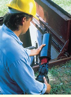
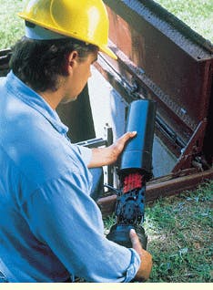
The FibrDome splice closure from 3M Telecom Systems Div. provides flexible splice capacity, holding up to 96 fibers in discrete splices or 432 fibers in ribbon splices.
Jerry Jackson is a product-development specialist, Udaya Kumar is a network apparatus product marketing supervisor, and Les Landers is an outside-plant technical-service engineer, all at 3M Telecom Systems Div. (Austin, TX).

