Alien crosstalk remains key cabling consideration for 10GBase-T deployment.
The IEEE 802.3 working group has submitted the 10GBase-T draft standard (D.3) to the IEEE Standards Association (IEEE-SA) for sponsor balloting. This major milestone marks the Ethernet industry’s recognition that the document is technically complete. Prior to publication, all IEEE standards must be approved by the IEEE-SA; the approval process includes an IEEE-SA sponsor ballot and a formal review assigned to a designated review committee (RevCom).
The sponsor balloting and review by RevCom are expected to be complete by this summer.
With copper structured cabling being more than 90 percent of the media installed in buildings today, 10GBase-T promises to lower the cost of 10-GbE interfaces by 50 to 80 percent because of the greater cabling simplicity and ease of deployment. 10GBase-T enables the more rapid adoption of 10-GbE into data centers and server farms, switch-to-switch connections in the core, and distribution networks.
While the 10GBase-T standard will continue to drive the usage and dominance of twisted-pair copper cabling for in-building network LAN and SAN applications, alien crosstalk remains the key cabling consideration for 10GBase-T deployment.
Cheaper bandwidth
The goal of the 10GBase-T project is to develop standards-based, low-cost 10 Gigabit for 100 meter reach over twisted-pair copper media. 10GBase-T is an important technology for private networks because it will lower the cost of 10-GbE interconnect for enterprise and data center customers by 50 to 80 percent in the first generation, and bring more radical cost decreases in subsequent generations. 10GBase-T also lets private enterprise network and data centers have more and cheaper bandwidth that runs on less expensive (compared with optical fiber), and easier to install and maintain, copper twisted-pair cabling.
Most 10-GbE connections deployed today are switch-to-switch. By populating fixed copper ports on line cards, switch vendors can increase port density by 50 percent, lowering the cost of the port, and enabling customers to use structured copper cabling, which is cheaper than either optical-fiber cabling or 10GBase-CX4 twinaxial cable assemblies. Furthermore, 10GBase-T will operate over the same cabling that supports industry standard IEEE 802.3af Power over Ethernet.
In short, 10GBase-T extends the Ethernet family of twisted-pair physical layer specifications to a data rate of 10 Gbits/sec-a factor of 10× over 1000Base-T-enabling network managers to scale their networks to 10 Gigabit speeds while leveraging their investment in installed copper cabling infrastructure. (The majority of in-building network cabling is twisted-pair balanced copper Category 5e or better.)
Link segments, primary parameters
10GBase-T link segment specifications are the minimum cabling requirements specified to support 10GBase-T operation. The link segment’s transmission parameters include insertion loss, return loss, pair-to-pair NEXT loss, power sum NEXT loss, pair-to-pair ELFEXT, power sum ELFEXT return loss, and delay. The link segment specifications are based on the Class E channel limits extended to an upper frequency of 500 MHz.1
In addition, alien crosstalk, crosstalk coupled “between” link segments, is specified for power sum alien NEXT (PSANEXT) and power sum alien ELFEXT (PSAELFEXT).
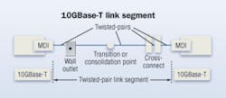
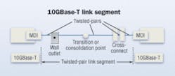
In addition to the cabling transmission and coupling parameters, an alien crosstalk to insertion loss ratio is specified to enable the evaluation of the combined effect of alien crosstalk to insertion loss. The link segment cabling topology, consisting of components (cables, cords, and connectors), is illustrated in the figure “10GBase-T link segment.”
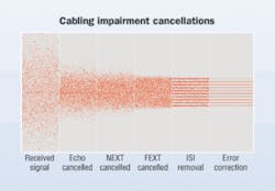
Alien crosstalk and insertion loss are the primary parameters to consider for 10GBase-T operation. Alien crosstalk is specified as power sum alien near end crosstalk (PSANEXT), power sum alien equal level far end crosstalk (PSAELFEXT), and power sum far-end crosstalk (PSAFEXT). The 10GBase-T signal-to-noise ratio (SNR) is primarily based on the ratio of the signal (insertion loss) to the alien crosstalk noise appearing at the receiver. The cabling impairments of return loss (echo), NEXT and FEXT within a cable are reduced to a small residual noise utilizing cancellation methods. The figure “Cabling impairment cancellations” illustrates the receive signal is initially indistinguishable from the noise, and subsequently completely recovered after cancellation and intersymbol interference (ISI) correction.
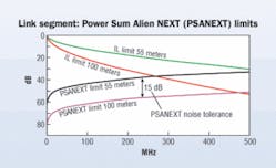
The 10GBase-T draft standard includes equations to determine the amount of PSANEXT loss and PSAELFEXT that a receiver can tolerate, based on the link segment insertion loss. In addition, the average PSANEXT loss and average PSAELFEXT “across the 4-pairs” is specified to account for the benefits of the channel coding, effectively averaging the noise “across all 4- pairs.” The derived PSANEXT loss, PSAELFEXT noise tolerances and the insertion loss are applied as limits in qualifying installed cabling as well as for specifying new cabling.
In the figure “Link segment: PSANEXT limits,” a link segment of 55 meters can tolerate 15 dB more PSANEXT noise than a link segment of 100 meters. Similarly, the PSAELFEXT loss limits determined from the PSAELFEXT to insertion loss requirements result in a 4.22 dB PSAELFEXT noise tolerance for the 55-meter link segment when compared to the 100-meter link segment.
Alien crosstalk margin computation
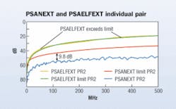
Link segments that can support 10GBase-T operation (i.e., have sufficient SNR margin) can still fail the individual pair limit lines. The figure “PSANEXT and PSAELFEXT individual pair” illustrates PSAELFEXT and PSANEXT measured on pair 2 of a link segment.
The PSAELFEXT fails the individual limit while the PSANEXT exhibits approximately 10 dB margin from the limit. The overall SNR margin for this link is sufficient to support 10GBase-T operation because the 10GBase-T receiver function does not discriminate between the individual PSAELFEXT and PSANEXT noise contributions. The receiver detects symbols from the “combined noise” and the transmitted signals on each of the 4-pair.
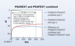
10GBase-T specifies an alien crosstalk margin computation to assess whether the cabling can support 10GBase-T operation should the individual pair limits not be met. The combined PSANEXT and PSAFEXT noise is calculated and subtracted from the combined alien crosstalk noise limit determined from the disturbed pairs insertion loss. The average “across frequency,” from 10 MHz to 400 MHz, of this difference is the alien crosstalk margin. The margin must be greater than “0” to utilize the cabling for 10GBase-T operation. Alien crosstalk margin is specified for each of the individual 4-pairs as well as the average “across the 4-pairs”.
The figure “PSANEXT and PSAFEXT combined” illustrates the calculated margin of pair 2, which had failed the individual pair limits. Although the pair had failed the PSAELFEXT limit, the alien crosstalk margin computation ensures that the total combined PSANEXT and PSAFEXT is limited to maintain the minimum signal-to-noise ratio; therefore, pair 2 will support 10GBase-T operation.
Alien crosstalk mitigation
Additional cabling guidelines for 10GBase-T deployment on balanced copper cabling are provided in Annex 55B, to be published with the 10GBase-T standard. This annex includes procedures to mitigate alien crosstalk should the link segment specifications not be met. ANSI/TIA/EIA-TSB-155, “The Additional Cabling Guidelines for 4-Pair 100 Ω Category 6 Cabling for 10GBase-T applications,” also provides procedures for alien crosstalk mitigation.
Alien crosstalk noise levels are dependent on the number and proximity of adjacent cables and connectors. It is reduced as the distance between adjacent cables and connectors increases.
From an application perspective, due to the wide bandwidth of 10GBase-T signals, the main concern is alien crosstalk noise from other 10GBase-T links. The relative contribution from other sources, such as 1000Base-T, is very small but may become significant if the disturbed 10GBase-T pair has a maximum insertion loss. In addition, increasing the length of separated patch cords will reduce the coupling voltage and reduce the coupled noise that appears back at the receiver.
Possible field-mitigation strategies include:
• Selective deployment of 10GBase-T utilizing non-adjacent patch panel positions (adjacency should also be checked at the rear of the patch panel);
• Reduce the alien crosstalk coupling in the first 5 to 20 meters of the horizontal cabling by separating the equipment cords and patch cords and unbundling the horizontal cabling. (A significant portion of the ANEXT coupling occurs in the first 20 meters);
• Choose equipment cords sufficiently specified to mitigate the alien crosstalk coupling, such as Category 6 ScTP and Augmented Category 6;
• Reconfigure the cross-connect as an interconnect;
• Replace connectors with Augmented Category 6.
Power backoff
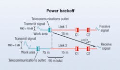
The 10GBase-T standard includes transmit power backoff (PBO) provisioning to adjust the transmit power levels based on the power level at the receiver. Power backoff reduces the amount of alien crosstalk coupled between link segments while maintaining the required power level at the receiver.
The “Power backoff” illustration shows two link segments in close proximity with horizontal cable lengths of 15 meters and 90 meters respectively. The transmit power of Link 1 is backed off by 10 dB, which effectively reduces the alien crosstalk coupled into Link 2 by 10 dB. The PBO level of 10 dB on Link 1 is allowed because the receiver power level of Link 1 is within the specified limits due to the relatively short link length of 15 meters. The Link 2 PBO level allowed is 0 dB due to the link length of 100 meters. Power backoff considerations are included in the alien crosstalk computation.
Cabling types and distances
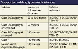
Cabling systems used to support 10GBase-T operation must meet the link segment requirements. The basis for the link segment specifications are to meet the 10GBase-T cabling objectives to support operation on at least 55 to 100 meters of Class E cabling, and at least 100 meters of Class F cabling. Other classes of cabling (e.g., Class D/Category 5e) may be supported as long as the cabling meets the link segment requirements. Class E/Category 6 UTP (unscreened) link segment distances greater than 55 meters are supported as long as the link segment specifications are met.
The 10GBase-T draft standard includes references to the applicable ISO/IEC and TIA-TR-42 cabling standards and guidelines. The IEEE 802.3 working group does not develop cabling standards, but works closely with ISO/IEC and TIA-TR-42 through the standards liaison process to synchronize the Ethernet physical layer technical developments and cabling standardization timelines. 10GBase-T provides references to the guidelines (proposed) in ANSI/TIA/EIA-TSB-155, ISO/IEC TR-24750, ANSI/TIA/EIA-568-B.2-10, and ISO/IEC 11801 Edition 2.1:
•ANSI/TIA/EIA-TSB-155: “The Additional Cabling Guidelines for 4-Pair 100-Ω Category 6 Cabling for 10GBase-T Applications” includes extended frequency transmission performance of Category 6 cabling from 250 MHz up to 500 MHz, alien crosstalk coupling between adjacent 4-pair Category 6 cabling channels, PSAELFEXT and PSANEXT, field test equipment and field test methods, and alien crosstalk mitigation.
•ISO/IEC TR-24750: The ISO/IEC technical report for installed Class E and Class F to support 10GBase-T is consistent with the ANSI/TIA/EIA-TSB-155 guidelines.
•ANSI/TIA/EIA-568-B.2-10: The standard for cabling and component specifications and test procedures to support the operation of IEEE 802.3 10GBase-T over 100 meters of structured balanced twisted-pair copper cabling includes extending the frequency range and adding requirements to those specified in ANSI/TIA/EIA-568-B.2-1.
•ISO/IEC 11801 Edition 2.1: The ISO/IEC 11801 Edition 2.1 is to specify new Class E and Class F specifications. The new classes are to be named Class EA and Class FA respectively, and will meet the technical requirements of 10GBase-T. Cabling NEXT specifications exceed those currently specified in ANSI/TIA/EIA-568-B.2-10.
Summary of technical elements
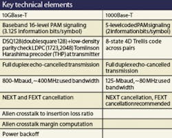
The key technical elements of 10GBase-T are the alien crosstalk specifications, including the PSANEXT to insertion loss ratio, PSAELFEXT to insertion loss ratio, alien crosstalk margin computation, power backoff, signaling, modulation rate, encoding, and start-up. The topology of operation for 10GBase-T is similar to 1000Base-T. Each of the 4-pairs is a full duplex channel supporting an effective data rate of 2500 Mbits/sec simultaneously in both directions, achieving an aggregate data rate of 10,000 Mbits/sec (10 Gbits/sec).CHRIS DiMINICO is a consultant at Solarflare Communications (www.solarflare.com), is the editor of the IEEE 802.3 10GBase-T link segment specification, and project leader for the TR42 PN-3-0134 developing a telecommunications system bulletin (TSB) in support of 10GBase-T. In addition, Chris is the liaison for the IEEE 802.3 working group to the TIA TR-42 Engineering Committee. BRUCE TOLLEY is director of marketing at Solarflare Communications, and a frequent contributor to the IEEE 802.3 Ethernet standards projects. He has served as an officer of the 10-Gigabit Ethernet Alliance and the Gigabit Ethernet Alliance.
