A long-standing tool allows for efficient testing of networks with a variety of connectors.
James Hayes / Fotec Inc.
Within the history of fiber-optic testing, nothing has been more of a challenge than adapting to the incredible variety of connectors used in fiber-optic networks. In almost 20 years of making fiber-optic test equipment, Fotec has made adapters for 82 different connector styles. Perhaps more astoundingly, more than 25 of these connector types are still actively used.
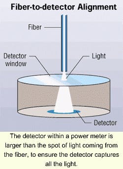
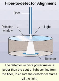
To adapt a power meter to a connector, you must mate the connector and align the fiber exactly to the detector in the meter. To make accurate power measurements, it is also necessary to capture all the light from the fiber, so the detector must be larger than the spot of light projected from the end of the fiber.
Some connectors make this alignment easy. Take, for example, the ST and SC connectors, in which the fiber ferrule extends well beyond the connector body and is a simple cylindrical design. Some connectors are very difficult: In the FDDI connector, the ferrule is recessed in a shroud that protects it, but also makes it impossible for anyone to get near the detector.
The latest challenge to the test-equipment manufacturer has been the new small-form-factor (SFF) connectors, especially the MT-RJ and VF-45. The fibers in these duplex connectors are very close together, mak-ing it extremely difficult to get the fibers close to the detector. The VF-45 fibers are recessed deeply in the plug and jack, while one side of the MT-RJ has alignment pins that protrude about 3 mm from the end of the connector. Both share a plug-and-jack configuration that complicates both instrument interfaces and testing procedures.
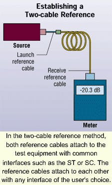
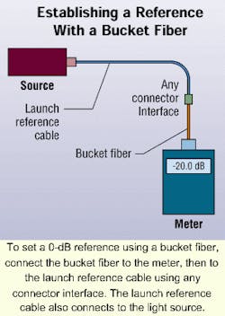
To test the loss of these connectors, you need to set a reference for 0-dB loss. To set such a reference, a user is supposed to connect a launch reference cable to a source and measure the output with the meter.
Because of the difficulty of mating some of the SFF connectors directly to a meter, many test-equipment manufacturers, and even connector manufacturers, have created test procedures that use a two-cable reference method. In this method, the second cable has a SFF connector on one end and another connector type (usually the ST or SC) on the other end. The ST or SC connector easily mates with the test equipment.
It is important to understand that network standards, such as the Gigabit Ethernet specifications and the TIA/EIA-568A Commercial Building Telecommunications Standard, call for the one-cable reference method because the loss of the connectors on either end of the cable plant must be accounted for when testing for the network's loss margin. The two-cable reference method reduces the allowable loss figure by the amount of loss in the reference cables' mated connectors. It also in-troduces a significant element of uncertainty-approximately 0.2 dB-in the measurement. For networks like Gigabit Ethernet, where the loss budget is small, the additional connector loss and measurement uncertainty can mean the difference between a good or bad cable plant.
Using the two-cable reference method has been justified because the method is included in several standards, most notably FOTP-171 for testing patch cords and OFSTP-14 for testing installed cable plants. Both standards are published by the Telecommunications Industry Association/Electronic Industries Alliance (TIA/EIA-Arlington, VA). While these standards indeed include such an option, the original meaning of that option has been lost, it seems. When we wrote these standards 15 years ago, the other authors and I had the same problem mating to many different connector types.
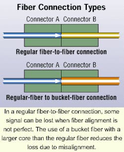
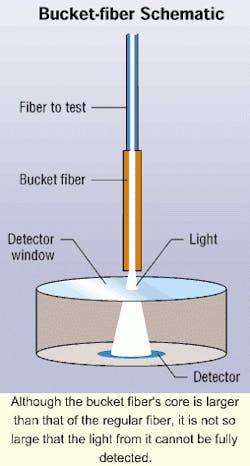
Because mating-adapters for meters were not always available 15 years ago, we experimented with options and developed the concept of the bucket fiber, which is a large-core fiber that can consistently gather all the light from the fiber under test. When we developed this technique, we used 50/125-micron fiber for testing singlemode fiber, and 100/140- or 200/250-micron fiber for testing most multimode fibers.
Using the bucket fiber is no different from using a detector with a pigtail, except that the bucket fiber is larger than the fiber being tested. The use of a larger fiber is intended to prevent variable losses due to typical connector mating characteristics of offset, angularity, and end gap.
The connection to a bucket fiber is not without loss, how ever, as you still have Fresnel reflections at the glass-air interfaces and some loss from diffusion at polished endfaces. But that is no different from the interfaces at the end of the fiber and the glass window on the detector in a normal power meter. The consistency of the connection from the smaller fiber to the larger fiber makes it possible to use it as a reference measurement without adding significant measurement uncertainty.
To use the bucket fiber with a meter, one needs to make a cable with the bucket fiber. Then terminate one end with a connector style that mates with the instrument, and terminate the other end with the connector type of choice. The interface to the meter will be through the bucket fiber for all measurements.
Once you have decided to use bucket fibers as adapters for SFF connectors, another problem arises. All fibers today have a 125-micron cladding diameter, so the connectors only have holes for fibers of that size. If you want to accommodate 62.5/125-micron fiber, you will not be able to find regular production fibers with a larger core size and the same 125-micron outside diameter. So to put the bucket-fiber concept into action for 62.5/125-micron fiber, you will have to special order a fiber with a larger core-100 microns in this case-and a thin cladding.
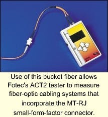
Fotec had a fiber made for this purpose, and fabricated bucket-fiber adapters for both MT-RJ and LC connectors for use with its ACT2 automated cable tester. This instrument, like most other automatic testers, comes with ST connectors only, limiting its use to connectors having 2.5-mm ferrules (ST, SC, FC, FDDI, and Escon). By using the bucket-fiber adapters, interfaces to both MT-RJ variants (with or without alignment pins) are possible. In addition, bucket fiber adapters can be built for optical-loss test sets (OLTSs), which have meters and sources in each unit. With an OLTS, plug the bucket fiber into the detector port and use a standard fiber in the source port.
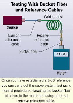
Now the testing process becomes much simpler than it has been. To set a 0-dB reference, attach a bucket fiber with the appropriate connector to the meter and launch cable. When you test, use the normal testing procedure, but keep the bucket fiber attached to the meter.
Using bucket fibers does not cure all the testing problems associated with SFF connectors. Although the bucket fiber is larger than the fiber being tested, it is still susceptible to errors caused by dirt on the connectors or abrasions on the end surfaces caused by multiple matings. Like all connectors, SFFs must be cleaned before measurements are taken, especially during the reference process. Also, you should inspect all reference cables with a microscope, and test them against other reference cables for loss. By doing so, you will weed out those that should be discarded or reterminated.
Although the bucket fibers do contribute loss, that loss is consistent. This consistency allows users to make relative measurements, which is really what all loss measurements are. But when testing networks, you must measure absolute power to test the transmitters' output and the receivers' input. Here, the bucket fiber will change the absolute calibration of optical power measured by the power meter. The amount of change may depend on the instrument itself, due to variations in mechanical interface, detector geometry, and packaging. Fotec intends to conduct studies of these calibration differences in the near future.
James Hayes is president of Fotec Inc. (Medford, MA), a manufacturer of fiber-optic test equipment and provider of the Cable U training series. You can reach him via e-mail at [email protected].
null
