Answers to many of the “why” questions associated with the installation and maintenance of UTP systems.
by James Andress
Most of us are familiar with the installation specifications that have been written for unshielded twisted-pair (UTP) cabling systems. These specifications include such topics as pair untwist, bend radius, and pulling tension. And while we are familiar with these standard requirements, many-especially those new to the trade-may wonder why such handling restrictions exist.
What happens if the specifications are not followed exactly? And why are the specifications more critical, and more restrictive, when transmitting higher data rates?
The key point of this entire article is: installation quality and correctness. They are vital, and they are entirely up to you.
Let’s first consider that the twisted pair was designed several decades ago to transmit a voice signal at 4,000 Hz. Over the past 15 to 20 years, to accommodate computer and data networking traffic, the design has been upgraded to allow transmission rates to go from 4,000 bits/sec to millions and potentially billions of bits/second. And, of course, installation methods have had to be upgraded accordingly.
The lexicon of data transmission
Throughout this article, I will use the terms “frequency,” “hertz,” “megahertz,” “megabits,” “gigabits.” Let’s ensure we know what they all mean.
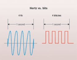
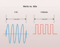
Hertz, or cycles per second, is an analog term. A hertz is one electrical energy cycle, above and below the center line, occurring in one second of time. In digital terminology, we use the term “bit,” which is one electrical energy pulse, above or below the center line or a combination of both, occurring in one second of time. Multiple hertz, or bits, can occur-four, forty, thousands, even millions-in a single second.
Any information that is transmitted involves the use of frequencies or bits, even including 60-hertz alternating current (AC) power. Information includes voice, music, radio, data, video, television, or even light, as in fiber optics. The more information we have to transmit, the more hertz, or bits, it takes to do so, and the more complex the technology required to transmit it.
In the computer and data business, all of the information seen on the computer screen is converted to electrical, or ones and zeros-a bit represented by a one and the absence of a bit represented by a zero. But there are other types of information sources, such as data transducers, industrial devices, and cameras that are frequency-based. In most of these cases, the frequencies are converted to bits before they are transmitted.
Often, there are significant differences between hertz and bits concerning how they are processed and convey information; but considering our discussion on cabling-installation specifications and practices, we can deal with the two terms interchangeably.
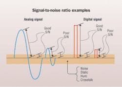
Another term we will use when talking about cable performance is signal-to-noise ratio, or SNR. This is simply a number expressing the difference between the power level of the information signal in a circuit, and the power level of the noise, hum, static, crosstalk, or other undesired interfering signals that are also in the circuit. SNR is expressed as a ratio; the larger the number, the better the circuit quality.
Directly related to SNR is bit error rate (BER). As the bit power level gets down close to the noise level, the receiver may have difficulty deciding if there is a one or a zero at a given period of time. If the receiver makes a mistake and reads a one instead of a zero, or vice versa, we have a bit error.
Twisted path of twisted pair
The twisted pair is a rather high-tech precision piece of hardware. Two areas of concern and how they relate to each other are: 1) the physical construction of the cable, and 2) the electrical characteristics of signal transmission.
The cable’s physical construction incorporates four significant characteristics:
- The diameter of the conductor and conductor material;
- The type of insulating material along with its density and thickness;
- The spacing between the insulated conductors of the pair as well as the spacing between the four pairs in the cable;
- The twist rate, or number of twists per inch, of the two conductors of a pair-but also the relative twist rate of each of the four pairs in the cable, each pair in a given cable having a different twist rate.
The electrical characteristics of signal transmission include the following items, each of which is complex and requires detailed explanation:
Resistance (R) is the resistance of the conductor to the passage of electric current. Resistance is constant along the conductor, controlled primarily by the size of the wire (the larger the wire, the less resistance it has) and the type of material (copper being the almost universal choice), and is measured in ohms(Ω). Another contributing factor to overall resistance is the type, thickness, and density of the insulation. Collectively, these resistance factors result in less signal received at the receiver, a poorer SNR, and a higher bit error rate.
Leakage or conductance (G) is the conductance of the insulation on each conductor to the passage of current leaking out to the adjacent conductor of the pair, or to the other pairs, or to ground. It is almost negligible in its electrical effect on the circuit, but it is there nonetheless and needs to be mentioned. Being very high in value, it is measured in megohms, or millions of ohms. It combines with resistance to weaken the signal along the pair, and is also constant along the conductor as well as controlled by the type of insulating material, its thickness, and its density.
Inductance (L) and its current-flow-inhibiting effect, inductive resistance (XL), are also significant characteristics. Inductance is the magnetic effect of alternating current signal flow in a conductor. It opposes the applied signal voltage, which in turn reduces the signal current flow, which then results in less signal into the receiver, and then to a poor SNR and poorer BER. Inductance is also constant along the conductor. But in this case, the higher the signal frequency or bit rate, the higher the current-inhibiting effect. Although inductance is inherent in any conductor, it is significantly increased when the conductor is curved or formed into a coil. The sharper the curve, or more rotations in a coil, or the smaller the diameter of the coil, the greater the inductance. These factors relate problems resulting from tight bends or kinks in the cabling.
Capacitance (C)-and its signal coupling effect, capacitive reactance (XC)-is the coupling effect of alternating current signal flow between electrical conductors and components. It allows signal coupling between the wires of a pair and between pairs. The common effect is crosstalk. Capacitance is inherent in a conductor or component. It is also increased by closer spacing or by a larger-size conductor or component. These factors relate to problems resulting from crushing, twisting, and bends that bring the conductors closer together.
Impedance (Z) is a frequently discussed characteristic. Expressed in ohms (Ω), it is a mathematical result of combining the values of resistance, inductive reactance, and capacitive reactance. It is also a design value of all major circuit components, such as transmitter, cable pair, and receiver. In designing and installing a circuit, try to keep all components and connections as close as possible to the design impedance, which in the case of network circuits is 100 Ω. In contrast, older data and telephone circuits were 600 and 900 Ω, respectively. From a practical viewpoint, when installation errors occur, such as tight bends and tie wraps, damaged cable or components, or poor joints, the component and overall design impedance is changed. And when all circuit components are not working at 100 Ω, one or more impedance mismatches occur.
These cause, at the location of the mismatch, signal reflections back toward the transmitter and a reduction in signal power going to the receiver. The worse the cumulative mismatches, the less the signal that is actually sent to the receiver, resulting in poorer SNR or BER. The signal reflections are called return loss, and are expressed in dB. The higher the dB number, the fewer installation problems and the better the circuit. All of these characteristics working together (or, in another sense, working against one another) determine the electrical performance of the UTP cable. They collectively affect the smooth flow of current, which makes up the data signal, through the cable.
High-tech cables are designed and constructed very precisely. The dimensions and composition of the conductors and insulation are carefully controlled. We are speaking of dimension tolerances of thousands-of-an- inch and material compositions in parts-per-million. This is also related to the relative placement of each conductor and its placement in the cable. So, any physical factor that distorts or affects these tolerances, even ever-so-slightly, changes the inductive and capacitive design parameters, which in turn affect the electrical reactive values, which then affects the flow of signal current through the cable. In these cases, impedance mismatches and reflections cause crosstalk, signal loss, noise, and then bit errors.
Let’s look at some of the installation specifications and see how even small mechanical distortions can affect transmission performance.
• Excess pulling tension--One action that can adversely affect signal transmission is exerting too much pulling tension or, stated differently, stretching the cable. The Telecommunications Industry Association sets the maximum pulling tension at 25 pounds. When installers exceed that limit, it results in elongation of conductors and insulation, which in turn reduces the diameter and density of those components (the insulation more so than the conductor). Exerting too much pulling tension also lengthens the twist rate of not only each individual pair but also the relative rate between each of the four pairs. In both cases, it would likely occur in isolated sections, not the total cable length, depending on the nature of the pull.
• Bend-radius violations--Violating miimum bend-radius limits by bending the cable too tightly or even kinking also has deleterious effects on signal transmission. Current specifications call for a minimum bend radius of four times the cable diameter in horizontal applications. Often, you will see two values: static and dynamic. The static value is the minimum bending radius of the cable after it is positioned or placed in its permanent location, with no further movement. The dynamic value is the minimum bend radius to be observed when the cable is being pulled and placed into position. This is the larger of the two numbers because of the added stress being placed on the cable as it is being installed. Ignoring the bend-radius specification results in stretching or elongating the pair twist on the outer edge of the cable, and compression or buckling of the smooth lay and pair twist on the inner edge. The normal concern is for cable in trays and raceways in long horizontal runs. The worst problem exists when excess slack is pushed back into a pullbox or outlet box, where very tight bends or even kinking could occur. Kinking, which can occur even when pulling the cable out of its supply box, is, of course, a severe case; once done, a kink really cannot be completely undone. In any case, a kink produces a severe inductive-reactance spike. It also likely will cause the conductors to be pushed closer together.
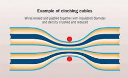
• Cinching too tightly--Fastening cables too tightly with tie wraps, clamps, or staples is a specification violation. Generally, specifications are rather subjective about this matter, but the overall creed is not to cinch the cables so tightly that the cable cannot be gently pulled under the fastener, or so that the tie wrap cannot be slid along the bundle. Failing to adhere to this guideline can result in crushing the cable, thereby increasing the density and reducing the diameter of the insulation surrounding the conductor, as well as the cable sheath. Additionally, it reduces the spacing between the conductors of a pair and the spacing among the four pairs of the cable. Finally, in extreme cases (as with a staple), the conductors can be bent or kinked.
• Insulation, jacket removal--Specifications also address the untwisting of the twisted pairs prior to termination. Specifically, installers are told to untwist as little as possible, but in no case exceed ½-inch or extend beyond the rear of the connector. And although it is unavoidable at the point of connectorization or punchdown, this action, even for a very short distance, untwists the conductors of the pair and sometimes increases the spacing between them. This concern is also true for the four pairs in the cable. Depending on the type of connector block, specifications vary concerning how much insulation may be removed from the conductor, as well as how much sheath may be removed from the cable. Generally, specifications say to remove only as much as is absolutely necessary. The ideal case is with punchdown blocks, where no insulation is cut back at all. Disregarding the specifications about insulation removal will cause a small change in the cable’s impedance, because the insulation on a conductor is one factor that determines impedance. Additionally, the sheath is the key factor in holding the four pairs in place and in relative position to one another. So, removing the sheath also removes this stabilizing factor.
• Effects on delay skew--Even delay skew, an electrical characteristic most closely associated with the material used to insulate conductors, is subject to variation, depending on installation technique. Workmanship involves terminating the pairs of the cable in such a way that each pair is cut to length in the connector or terminal block. Mechanically, this avoids having extra-length pairs bunched up in the connecting area. In so doing, however, each of the four pairs ends up having a slightly different length. Specifications call for a 45-nanosecond maximum delay skew, among the four cable pairs, along a 100-meter span. That is the difference in time, among the four pairs, one to another, for the signals to propagate through the cable from the transmitter to the receiver. Erroneous installation methods can have a detrimental effect. Very high data-rate signals that are divided into four parts must be recombined in the proper order, or sequence, at the receiver so that the original signal can be properly detected and decoded. If there is too much difference in the relative data length of each of the four pairs, some bits will be delayed too much and get recombined out of their proper order, with resultant bit errors. The specification allows for differences in propagation delays due to the different twist rates on each of the four pairs; however, when cutting the four pairs to the same length, extra care must be taken so that the retained slack does not become kinked nor violate the minimum bend radius specification.
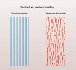
• Cable combing--Combing the cable installation-installing or laying the cables in a tray neatly, side by side-is a practice not addressed in specifications yet, but may soon be. It is, without question, a technical-performance concern. In long runs of several cables, it is customary to install the runs in an orderly, straight, and side-by-side manner. This technique provides a very neat and professional appearance; however, particularly at very high data rates, it also allows the inductive reactance coupling of electric fields surrounding the conductors to more easily combine and build up, and the capacitive reactance coupling between the conductors to further minimize. The main concern is not totally between the four pairs in a given cable, but the cable-to-cable coupling directly affecting alien crosstalk. By using a random lay, the cables are constantly changing their relative spacing and crossover position. This reduces the chances for a long exposure to inductive and capacitive coupling. In fact, coupling fields can actually experience some cancellation as they wander in a random fashion along the cable tray or rack.
Even if you have followed the installation specifications perfectly, it is more difficult to get good BERs at high data rates than at lower rates. (Please note that the following formulas only illustrate relationships, and should not be used for actual circuit calculations). Critical factors are inductive and capacitive reactance.
Remember that inductance is constant along the conductor; however, the higher the signal data rate, or frequency, the greater the reactance, or current-inhibiting effect, or inductive reactance XL. As the data rate, frequency, or inductance increases, XL also increases.
This can be expressed mathematically with the following formula: XL=2ΠfL. 2Π is a constant with a value of 6.28; f is the data rate or frequency; and L is the inductance of the pair or other component at a given point in the circuit.
XL exists even in all good circuits, but its effect is made worse by problems with too-tight bends, kinks and, to some extent, with staples and tie wraps.
Capacitance is also constant along the conductors. But in this case, the capacitive resistance, XC, in contrast to XL, decreases as the signal data rate increases. So, with a smaller XC, or opposing effect to signal coupling, crosstalk can increase as the data rate, or frequency, increases.
This also can be expressed: XC = 1/2ΠfC. 2Π is the constant 6.28; f is the data rate or frequency; and C is the capacitance between the pairs or other components at a given point in the circuit.
Like XL, XC is a factor in well-established circuits, but its effect can easily be made worse by problems with crushing, twisting, bends that bring the conductors closer together, and long installation runs of combed cable.
The resistance effect also increases with higher data rates, although it is not quite as contributory as is inductive reactance. The increasing effect is due to the way the higher-frequency energy propagates along a conductor-a condition called skin effect. Also of importance is the chemical composition of the insulating materials, which affects the impedance characteristic of an insulated conductor. Higher frequencies are attenuated more so than the lower ones. This effect is related to the insulation dielectric constant. (Please note that when discussing signal transmission, most specifications and other literature refer to resistance factor as attenuation.)
Quality control
Installation quality and correctness lead directly to maximum signal-to-noise ratios and minimum bit errors. In that sense, system performance is up to you-the installers and operators of cabling systems.JAMES ANDRESS is an engineering consultant for telecommunications at New Mexico State University’s Physical Science Laboratory.
