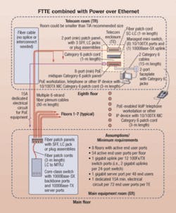
A new architecture known as fiber-to the-telecom enclosure capitalizes on the bandwidth capabilities of optical circuits.
Each year, information technology (IT) managers incorporate more sophisticated voice, data, and video equipment into enterprise applications. The structured cabling system (SCS) industry is continually challenged to develop new and more cost-effective connectivity to such systems.
Several committees within the Telecommunications Industry Association (TIA) TR-42 Engineering Committee responded to this need with new standards enabling a new architecture-fiber to the telecom enclosure (FTTE)-that takes advantage of fiber’s capabilities by bringing increased bandwidth closer to the user, while also improving system performance.
Evolution of standards-based SCS
The first TIA-568 commercial building cabling standard, ratified in 1991, met the growing need for an orderly and systematic way to install and manage premises cabling. Because fiber was not yet used for many applications in the enterprise, TIA-568 was developed based on the performance capabilities and practical limitations for copper; hence, the hierarchical star architecture and the 100-meter horizontal distance limit.
In 1995, the TIA released TSB-72, establishing guidelines to take advantage of fiber’s extended distance capability and move the telecommunications room (TR) electronics into the equipment room (ER). This established the basis for an all-fiber, or fiber-to-the-desk architecture. In 2001, TSB-72 was incorporated into the current version of the 568 standard, TIA/EIA-568-B.
To date, acceptance of fiber-to-the-desk has been limited, and a more gradual transition to fiber is likely. Consequently, in 2005, two separate standards-TIA/EIA-569-B and 568-B.1, Addendum 5-established the foundation for the new telecommunications enclosure (TE) implementation and paved the way to a new SCS architecture that brings the high performance of fiber closer to the user while leveraging the strengths of copper-based transmission.
TEs meet growing requirements
IT and telecommunications managers who deploy SCSs have much in common:
It is now possible for a single SCS architecture to cost-effectively meet all of these requirements.
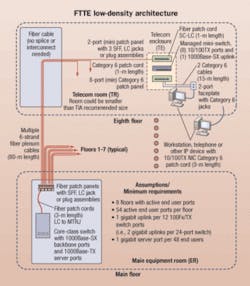
FTTE is a standards-based commercial building SCS architecture that extends the fiber backbone from the equipment room, through the riser and the TR, and out directly to a TE installed in a common space that serves a number of users in their work area. Its implementation is based on the new TIA/EIA-569-B standard covering pathways and spaces, which defines the TE “space,” and on TIA/EIA-568-B.1 Addendum 5, which defines the TE cabling.
The FTTE architecture allows for any media choice from the TE to the work area; it may be unshielded twisted-pair (UTP) copper, multimode or singlemode fiber, or even wireless if an access point is installed in or near the TE.
Hierarchical star vs. FTTE
To help users compare FTTE architectures with the traditional hierarchical star architecture, the TIA Fiber Optics LAN Section (FOLS) included two versions of the architecture into the latest version of its premises cost model, which is available at the group’s Web site. The cost model lets users compare several architecture alternatives by selecting their sample scenarios or by customizing the model parameters to reflect their own installation. Users can also modify the cost model by inputting their own parameters and local costs. The active electronics, passive cable, and connectivity costs used in the sample scenarios represent aggregate costs that were largely derived from a public database (www.peppm.org), which is used by educational and governmental customers.
The cost and performance data described here is based on the latest FOLS cost model:
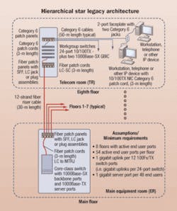
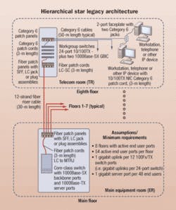
In the traditional hierarchical star design, core-class Ethernet switched with 1-Gbit/sec fiber backbone ports connect to the TRs, and 1-Gbit/sec copper backbone ports connect to the other servers. In the TRs, workgroup-class switches from Tier 1 manufacturers are configured with twenty-four 10/100TX copper ports to the work areas. In addition, each workgroup switch is configured with two 1-Gbit/sec fiber uplink ports using modular GBIC (gigabit interface converter) fiber transceivers.
In the work area, internal PC copper network interface card (NIC) electronics are assumed, since they are typical and standard today. Cabling from the equipment room to the TRs includes standard 50/125-µm multimode fiber having 500 MHz∙km bandwidth at both the short (850-nm) and long (1310-nm) wavelengths. Category 6 UTP cable and connectivity are used from each TR to the work areas. This configuration reflects what is being used in most enterprises today.
For the FTTE architecture, as with the hierarchical star, core-class Ethernet switches from Tier 1 manufacturers are used with a 1-Gbit/sec fiber backbone and 1-Gbit/sec server ports. Both low-density and high-density FTTE designs are modeled. The primary difference is the issue of one or two inexpensive 8-port Ethernet mini-switches in the low-density implementation. These switches have eight 10/100 copper ports and one 1-Gbit/sec fiber uplink.
The high-density FTTE design in the model uses commonly available 24- or 48-port switches. These switches are configured with one 1-Gbit/sec uplink port per twelve 100Base-TX user ports. This relatively high work area-to-backbone port ratio provides better performance than is typically provided to enterprise users.
Performance advantage
High performance is an additional key benefit of FTTE. Both the low- and high-density FTTE options provide excellent performance in terms of bandwidth delivered to the work area. In many enterprises, 32-port switches are typically deployed and configured with one 1-Gbit/sec fiber uplink to the ER. This provides each workstation approximately 31 Mbits/sec of average throughput (1 Gbit/sec divided by 32 ports). Even if the 32-port switch is configured with two 1-Gbit/sec fiber uplinks, the average throughput available to each workstation is only 63 Mbits/sec.
In each of these cases, the backbone has insufficient capacity to carry the full traffic from all workstations, each running at their maximum rate of 100 Mbits/sec. This design results in an “oversubscribed” switch (32 ports x 100 Mbits/sec = 3.2 Gbits/sec required, where only 1 or 2 Gbits/sec is available).
The FTTE low-density design offers the highest performance to the work area because the 8-port mini-switch is totally non-blocking. That is, excess “capacity” exists as 200 Mbits/sec remains on the 1-Gbit/sec fiber backbone to the TR when all eight ports are operating at 100 Mbits/sec. The switch is able to provide connectivity to all eight workstations requiring 100 Mbits/sec simultaneously, because the aggregate total from the eight workstations is 800 Mbits/sec and the uplink can provide 1,000 Mbits/sec. The mini-switch in the FTTE low-density design is “non-blocking” or “undersubscribed.” The high-density FTTE design represents a sacrifice in performance, but offers increased installation savings.
The cost advantage
Compared to the hierarchical star, FTTE architectures offer the potential for significant cost savings. When low-density FTTE is deployed, the cost model estimates that the total costs for network electronics, fiber and copper cable and connectivity, as well as labor and the TR can result in a per-port savings of more than $198 compared to the hierarchical star.
This cost scenario would result in total savings of more than $85,000 for the “model” eight-story building. In addition, this design offers the highest performance of any SCS design. The high-density FTTE system could save even more-in excess of $272 per port, or more than 41% compared to the hierarchical star architecture. The total network savings for a high-density FTTE system is a projected $117,700. The FOLS encourages all users to customize the cost model with their own numbers to find the most accurate estimates for their installations.
Selecting the TE
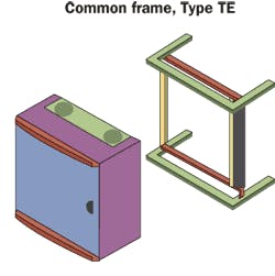
Since the TE is the heart of the FTTE architecture, its selection requires care. Several manufacturers offer enclosures suitable for this application, and we expect more will be introduced as the benefits of FTTE become more widely recognized.
The TE must provide sufficient capacity, with the standard of measurement being the EIA rack unit (RU) to house the required active electronics and passive cable and connectivity products:
