Following design rules and watching data traffic ensures top Ethernet and Fast Ethernet performance.
Stephen Stange / Transition Networks
Since the ansi/tia/eia-568a Commercial Building Telecommunications Cabling Standard was approved, much emphasis has been placed on ensuring that the physical cabling plant is done correctly. Adhering to the guidelines found in the standard provides a structured cabling plant that should work well with many different networking protocols. But for all of its benefits, the standard does not address--nor should it address--all of the issues associated with installing a properly functioning network.
In fact, a network fully compliant with the tia/eia-568a standard but which ignores some basic networking issues will fail to deliver the performance expected. Most of the networks being installed today are 10-megabit-per-second Ethernet networks, with Fast Ethernet daily gaining in popularity. Both Ethernet and Fast Ethernet are shared-media topologies: When one node transmits, all other nodes in the same segment, or collision domain, hear the transmission. If two devices try to transmit at the same time, a collision results, and both nodes involved need to try again. This attribute of shared media adds more requirements to Ethernet networking that are not addressed in the tia standard.
Collision domains
A collision domain is a group of Ethernet or Fast Ethernet devices directly connected by repeaters. Collision domains are separated by switches and routers, which allow separate collision domains to communicate with each other. Only one device within a collision domain may transmit at any one time. When a device is transmitting, all other devices in the collision domain listen. Both Ethernet and Fast Ethernet use a collision-sensing standard protocol known as carrier sense multiple access with collision detection (csma/cd), which allows multiple devices to access a shared Ethernet or Fast Ethernet network.
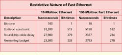
For each collision domain, the csma/cd protocol determines which device has access to the network. The csma allows a node to transmit if there is no existing traffic on the network. The CD will detect simultaneous transmissions and stop all traffic. All devices will then re-send at random intervals, allowing each node to retransmit successfully unless another collision is detected. However, collision-domain size is limited. It is measured in terms of bit-time instead of in distance because a signal on the network has a constant speed relating to the type of medium it is traversing, be it optical fiber or twisted-pair cable. Bit-time is measured as the time it takes the smallest allowable packet to make the round trip from the transmitting node to the furthest node in the collision domain. The smallest allowable packet size in Ethernet or Fast Ethernet is 64 bytes (512 bits).
If a node is too distant from other nodes in its collision domain, then packet transmissions may not be able to make the entire round-trip distance in the amount of time needed to ensure that collisions are heard by all devices on the network. This situation is referred to as a "late collision," which increases the possibility of lost packets and degrades overall network performance. This property of shared media gives rise to several rules and concerns, which are independent of the type of transmission medium.
Excess utilization
The first and perhaps most obvious concern is that the more nodes there are in a collision domain, the greater the chance for a collision. Any properly installed and configured Ethernet local area network (lan) will have some collisions. With collisions comes retransmission, and with retransmission comes more traffic, and with more traffic come more collisions.
The point is obvious: An Ethernet lan needs to be designed to keep traffic on a segment below some acceptable level. A completely shared 1000-node Ethernet network may meet the structured-cabling requirements, but its performance will be abysmal. A good rule of thumb is 30% utilization, which correlates to about 50 nodes. (Actual numbers will vary based on the exact applications.) Above that, overall throughput actually starts to decrease rather than increase.
So how do you keep utilization on a segment within acceptable limits? Deploying some kind of Ethernet switching or bridging is the most practical approach. Many designers will use a switch at the main distribution center (mdc) to break the Ethernet lan into separate segments for each department or work group. Each switch is connected via backbone cabling to a hub in the telecommunications closet (TC). In larger installations, the network may need to be further subdivided.
5-4-3 design rule
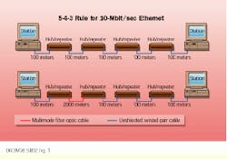
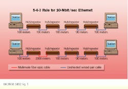
In 10-Mbit/sec Ethernet lans, another rule of thumb must be kept in mind: the 5-4-3 rule, which stands for five segments, four repeater hops, and three populated segments. The last part--three populated segments--applies only to 10Base-2 coaxial-cable installations. But because coaxial cable generally is not being installed anymore, the first two elements (five segments and four repeater hops) must be understood and followed.
This rule means that between any two nodes in a collision domain, there can be no more than five wiring segments and four repeater hops. How does this rule apply to structured wiring? If two or more hubs are cascaded in a single wiring closet and then connected to other hubs in either the mdc or in an intermediate distribution center (idc), the limit of four hops easily could be exceeded. When interconnecting hubs in the same TC, stacking should be used instead of cascading.
Stacked hubs operate as one repeater unit. This way, more than four hubs can be interconnected without violating the 5-4-3 rule. Most vendors provide a stackable hub. These hubs employ a proprietary stacking connection to link together the hubs. Stacked hubs also provide better throughput than cascaded hubs, since the signal only travels through one repeater. Typically, six or more hubs can be stacked vertically and still function as a single repeater. Any time switches are used, the collision domain is divided (with each port on the switch in its own segment), allowing the 5-4-3 rule to be restarted, which affords greater flexibility and performance.
512-bit-time design rule
The 5-4-3 rule applies only to 10-Mbit/sec Ethernet. In Fast Ethernet, however, the 512-bit-time limitation on the round-trip delay is the limiting factor. Bit-time distances in Fast Ethernet are limited to one-tenth the size of Ethernet`s bit-time distances. In Fast Ethernet, the round-trip delay for each device as well as the cable must be taken into account when designing the network.
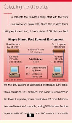
There are two classes of repeaters (or hubs): Class I and Class II. These repeater classes are divided according to the delay they introduce into the network. The faster of the two classes, the Class II repeaters, must have no more than a 92-bit-time delay. In addition, Fast Ethernet networks may incorporate no more than two repeaters in one collision domain.
How does the 512-bit-time rule apply to a structured cabling environment? Following are two typical cases.
Single-building application
The first case is a single-building installation with one mdc and several TCs, each with a backbone connection to the mdc. Also assume that the maximum distance between the mdc and TCs is less than 100 meters. Hubs in the mdc cannot be linked to hubs in the TC without using some sort of bridging. The best solution would be to use stacking hubs in the TC that are linked to a multiport Fast Ethernet switch in the mdc. That would place each TC in its own collision domain.
The calculation of the maximum size of the collision domain to ensure compliance with the 512-bit-time rule would be as follows: Start from the switch port, which functions as a dte (data terminating equipment); this adds 50 bit-times. Assume a maximum backbone length of 100 meters (a restriction placed by this example and by the use of copper instead of fiber cable); this adds 111 bit-times. If the hubs in the TC are stacked, they are probably operating as a Class I repeater, for 140 more bit-times. Assume a maximum of 100 meters of cable in the horizontal, which will add another 111 bit-times. And finally, the workstation adds another 50 bit-times.
The total (50+111+140+111+50) is 462 bit-times, well within the required 512-bit-time limit. If a multiport Fast Ethernet switch is not available, a hub along with a 2-port bridging device could be added to each backbone connection to separate the collision domains and provide the same round-trip delay figures.
Campus environment
The second case is a bit more complex and involves an mdc in one building, which is connected to an idc in a second building 2 kilometers away. The idc in that building is then connected to several TCs, which are then connected to work areas.
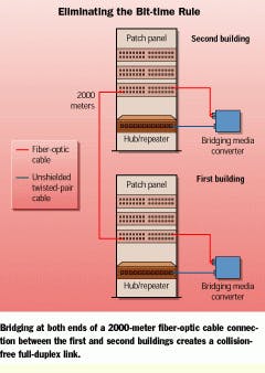
The first point of interest is the backbone connection between the two buildings. It is possible to calculate the round-trip delay of this segment, and at 1-bit-time per meter of fiber, it is easy to see that the 2000 meters of fiber will far exceed the 512-bit-time rule. But this rule is rooted in the fact that the media is shared and that there can be--and will be--collisions. If collisions can be eliminated, the 512-bit-time rule can be eliminated as well. By bridging at both ends of the link, a full-duplex link can be created. A full-duplex link has no collisions and therefore is not constrained to 512 bit-times.
So how does this implementation work? In the mdc, a multiport Fast Ethernet switch is the best solution. If price is a consideration, the product probably will have 100Base-TX ports. By using a 100Base-TX-to-100Base-FX media converter, it is possible to connect the switch to the fiber segment.
At the idc, a decision then needs to be made: If the link is going to terminate in a multiport switch, then a 100Base-TX-to-100Base-FX media converter can be used to make the connection. However, if the link is to terminate into a hub, then a bridging media converter is required. A bridging media converter not only converts the media type from 100Base-TX to 100Base-FX, but also provides a bridging function between the two ports. This bridging function is required when connecting to a hub because hubs are inherently half-duplex devices. This choice implies collisions, which further mandates the application of the 512-bit-time rule. The bridging function in these converters provides a half-duplex 100Base-TX connection to the hub and full-duplex 100Base-FX connection for the backbone link.
Once inside the remote building, all those concerns in the single-building example apply. Care must be taken not to place too many users on a single segment, and all segments must remain within the 512-bit-time limitation.
Centralized cabling
One final structured application needs to be considered. The telecommunications systems bulletin tsb-72, "Centralized Optical Fiber Cabling Guidelines," calls for fiber runs from the main crossconnect to the work area with no intervening active electronics. The distances allowed in this document are up to 300 meters. For a 10-Mbit/sec Ethernet installation, the 5-4-3 and the 512-bit-time design rules are sufficient. The only other consideration here is the cost associated with the active electronics, much of which can be reduced through the use of media-conversion technology.
Centralized fiber-optic cabling for Fast Ethernet needs further attention to detail, however. Going back to the 512-bit-time rule, calculate what can be done before bridging needs to be employed. Assuming every network has a server or other network device connected to the mdc, the calculation should start at that device.
A piece of equipment such as a server or router will introduce a 50-bit-time delay. If you assume a minimum patch cable of 15 meters, another 15 bit-times are added. The hubs in the mdc would be stacked and more than likely add 140 bit-times. (Use 92 bit-times if the hubs operate as Class II repeaters when stacked.) The 300 meters of fiber will add 300 more bit-times, and the workstation will add 50 more bit-times. The total (50+15+140+300+50) is 555 bit-times. If none of the runs is more than 257 meters and all the equipment and workstations come with fiber connections, everything will be okay. But neither of these conditions is likely to be true all the time, so a solution needs to be provided.
Again, some sort of bridging needs to be deployed to stay within the 512-bit-time rule in a centralized fiber-optic cabling installation. Also, all the equipment to be used will not always have fiber connections, so media converters may be needed. Combining those two requirements, a bridging media converter is often the best solution. If the network is large, multiport bridges that break the segments into smaller collision domains also are required.
Today`s structured-cabling standards provide a robust and well-managed platform for implementing various lans. But for these networks to provide the desired performance, adherence to a few additional guidelines is required. Making sure each segment does not carry too much traffic, following the 5-4-3 rule for Ethernet, and staying within the 512-bit-time limitation for both Ethernet and Fast Ethernet will go a long way toward providing a cabling solution that delivers on its promise.
The 5-4-3 rule dictates that there be no more than five cabling segments and four hubs/repeaters between two stations.
Stephen Stange, a product manager at Transition Networks (Minneapolis, MN), is vice chairman of the tia Fiber Optics lan Section`s standards committee and has more than 10 years` experience in the local area network communications industry.
