Shielded or screened cable is increasingly being used to reduce the amount of noise that escapes from--or is coupled into--a cabling system
Ned A. Sigmon
AMP Inc.
As network transmission speeds increase and concerns about electromagnetic radiation (EMR) and electromagnetic interference (EMI) grow, the subject of shielded cabling comes up more frequently. The topic can be confusing because the terminology has been variable and the status of the applicable standards has been in flux (see "Shielding Terminology Can Be Confusing," page 45, and "Shielded 100-ohm cabling standards need to be set," March 1996, page 50). Screened twisted-pair (ScTP) cabling, the medium currently being specified by a committee of the Telecommunications Industry Association (TIA) (Arlington, VA), is a 4-pair, 100-ohm cable that has at least one overall foil-laminate shield and tinned-copper drain wire in contact with the shield.
In many countries, including the U.S. and European countries, control of electromagnetic emissions is required by law. In the U.S., for example, the Federal Communications Commission (Washington, DC) has specific limits on how much energy can be radiated from electronic equipment.
Today, manufacturers of 100- or 120-ohm local area network equipment generally design for, and demonstrate compliance with, unshielded twisted-pair (UTP) cabling. In this case, screened cabling is, theoretically, not required. However, the emissions or immunity performance of UTP cabling is highly dependent upon the balance of both the cable and the connecting hardware. While a perfectly balanced UTP system would have no emissions or immunity problems, real-life cables, connecting hardware and cable terminations are not perfectly balanced.
There are currently no correlations between balance and emissions or immunity that define what degree of unbalance can be tolerated. There are also no specifications that can be used to control the balance of UTP components or cabling systems. Therefore, there is no guarantee that the cabling used to demonstrate compliance in a laboratory accurately reflects the variability of real-life installations.
Unless an end user monitors emissions or is subjected to monitoring by a government agency, the most visible benefit of ScTP cabling is likely to be a reduction in noise from outside sources. As transmission speeds and frequencies increase, communications systems tend to become more vulnerable to noise.
The use of UTP cabling becomes a tradeoff between maintaining an acceptable signal-to-noise ratio and controlling emissions. As frequencies increase, signal voltages must be kept to a minimum to control emissions. At the same time, increased attenuation of the cabling reduces the voltage level at the receiving end. The result is less margin between the attenuated signal and the overall noise from crosstalk and external sources. One of the primary benefits of shielding, therefore, can be to override the variability in installed twisted-pair cabling balance and add signal-to-noise margin to counteract particularly noisy environments or ensure the integrity of critical circuits.
Specifying an ScTP cabling system
The specifications for 100-ohm ScTP transmission performance in the proposed Telecommunications Systems Bulletin have been designed to allow ScTP to be substituted for 100-ohm UTP in most UTP-based applications. ScTP, then, will generally meet the same TIA/EIA-568A requirements and guidelines defined for UTP.
However, the proposed Telecommunications Systems Bulletin on screened cabling identifies several key differences:
Because ScTP cabling constructions tend to be stiffer than UTP cable, the recommended minimum bend radius is 8 times the cable diameter (or approximately 2 inches) instead of 4 times the diameter allowed for UTP cable.
Because the presence of the shield requires thicker conductor insulation to meet the same impedance and attenuation specifications as UTP cable, it is not currently practical to make a 24-gauge American Wire Gauge screened cord that will fit modular plugs of standard configuration. Instead, 28 AWG ScTP cords are allowed and are typical for this type of cabling.
The smaller 26 AWG conductors will increase cord attenuation to as much as 1.5 times that of a 24 AWG solid-conductor distribution cable. By comparison, a 24 AWG stranded cord may result in 1.2 times greater attenuation. The difference means that if the overall length of the cabling link is greater than 85 meters (279 feet), the combined cord lengths may need to be shortened from what is allowed in TIA/EIA-568A to ensure the same cabling channel performance.
Grounding the system
Grounding questions seem to cause the most confusion among potential ScTP users, particularly those who have had little or no prior experience with shielding. These questions are all interrelated and can be answered by taking a closer look at the philosophy of shield grounding.
First of all, there should be no question that the shield needs to be grounded. This is essential if the shield is to provide optimal protection against emissions or noise. The TIA/EIA-568A standard states that shielding should be grounded wherever it is used. The proposed bulletin on ScTP cabling requires that the cabling shield be grounded in the wiring closet. The ISO/IEC 11801 standard of the IEC and International Organization for Standardization (Geneva, Switzerland) points out that in order for shields to improve electromagnetic-compatibility performance, they have to be properly bonded--a term that describes a metal-to-metal connection to ground.
That brings us to the question of how often to ground, or whether to use single-point or multipoint grounding. In theory, single-point grounding works best at low frequencies, while multipoint grounding is better for high frequencies. Ideally, multipoint grounds should be spaced no farther apart than every one-sixth of a wavelength. However, at a frequency of 100 megahertz, that would require grounding every one-half meter, or 1.6 feet, which is impractical for a building cabling system.
In addressing this situation, the proposed TIA/EIA bulletin on ScTP cabling adopts the position of a U.S. military standard, MIL-STD-1857, which states that when grounding at one-sixth wavelength intervals is impractical, shields should be grounded at each end. This practice has been used successfully for STP cabling since the mid-1980s and has generally been accepted throughout the world for shielded building cabling.
The practice of grounding a shield at each end normally assumes that the workstation end of a horizontal shielded cable run will be grounded through the equipment connected to that end. Typically, this is done through a shielded equipment interface connector, usually a shielded modular jack, where the shield is grounded directly to the equipment chassis and chassis ground. The proposed bulletin and other cabling standards do not control the equipment interface, so the user must ensure that any equipment or network interface cards used with a shielded cabling system provide such an interface and ground path.
The wiring-closet end of the cable shield is required by the proposed Bulletin to be grounded to a telecommunications grounding bus that conforms to the TIA/EIA-607 standard on telecommunications grounding and bonding requirements. Typically, the cable shield is grounded through a connector to a patch panel, which is grounded to a rack. This rack is then grounded to the telecommunications grounding bus. The rack, and sometimes the panel itself, is provided with a grounding lug to which the installer may connect a copper grounding conductor.
The wiring closet ground should be the only ground for the shield of the generic cabling--that is, the installed cabling with no equipment attached. The cabling should not be grounded at the outlet, because this would introduce a third ground point that may be more poorly controlled than the other grounds. It may be at a different voltage potential and, therefore, more likely to create a ground loop. If the telecommunications outlets are mounted in metallic boxes that are connected to metallic conduit, steel framing or some other potential ground path, the shield of the cable and connecting hardware must be insulated from contact with these components.
Grounding the cable shield at both ends implies that the shield must provide a continuous path from end to end. It also implies that the shield will provide essentially full coverage from end to end, which is the intent of cabling standards. The proposed bulletin, in fact, specifies that the system be fully shielded from end to end. ISO/IEC 11801 requires that all cabling components be shielded and that the shielding be continuous for the complete channel, including the work-area equipment cables and equipment attachments that are not part of the generic cabling.
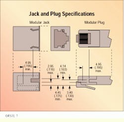
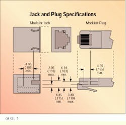
From a practical standpoint, a lack of shielding on any section of the cabling, or a break in the shielding, will compromise the effectiveness of the shield on the remainder of the system. However, if the user is not careful in selecting components, there can still be a problem with maintaining shield continuity through equipment, outlet and patch panel connections. Before the proposed bulletin on screened cabling, there was no industry standard controlling the shield contact interface between shielded modular plugs and jacks. Manufacturers have used proprietary designs with no assurance that a plug from one manufacturer would provide shield continuity when mated to a jack from another manufacturer. The proposed bulletin includes a compromise set of minimal dimensions that would ensure continuity.
Note, however, that these dimensions ensure only line-to-line contact in the axial direction. They do not allow for any wiping action between the contacts during mating and unmating. Wiping action is generally recommended to remove a buildup of contact contaminants. To provide sufficient wipe, the contact designs should allow an additional 2 millimeters (0.078 inch) of overlap.
Until the Telecommunications Systems Bulletin is complete and manufacturers have had time to react to it, the user or installer should verify that the connector manufacturer has complied with the proposed requirements or that the connectors provide shield continuity when mated.
Installing a screened cabling system
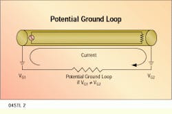
One concern about grounding the shield at both ends is that this may lead to ground-loop problems. A ground-loop circuit is created by the combination of shield and ground path. If the voltage potential of the ground points is at a different level, a current may be created in the circuit. The ground loop could pick up noise from external electrical fields and, depending on the efficiency or transfer impedance of the shield, a noisy current on the outside of the shield could potentially couple the noise into the conductors inside the shield.
To guard against this, the proposed TIA/EIA bulletin requires that the installer measure both the resistance and the voltage potential between the end of the cable shield at the work-area outlet and the green grounding conductor of the electrical outlet that would supply power to the workstation equipment. The resistance must measure less than 3.5 ohms and the voltage should be less than 1 volt (root-mean-square).
These are the same requirements that have been applied successfully to STP cabling installations since the mid-1980s. If the requirements are met, there is no significant ground-loop current. If they are not met, then the situation must be rectified before the cabling system is used.
Sometimes the resistances and voltage potentials are measured after the shielded cabling is installed. However, some European countries take the more proactive approach of requiring that the voltage potentials between the wiring-closet telecommunications ground and the electrical outlet grounds be measured before installing the telecommunications cabling. If there is more than 1V RMS, optical fiber instead of shielded twisted-pair cable should be used.
This approach is particularly applicable where existing buildings are being recabled. While the measurement may occur late in a new construction and specification process, new buildings with properly bonded steel structures tend to exhibit no ground-potential problems.
The effectiveness of a shield ground depends on the quality of the shield termination at the connecting hardware. A poor termination can inhibit proper grounding and reduce the overall effectiveness of the shield. A good shield termination is one that provides a low impedance path to ground, with emphasis on the word "impedance." Continuity alone does not ensure a good termination. Even low resistance is not enough. Low impedance requires both low resistance and low inductance.
While it has sometimes been a practice in the past to terminate only the drain wire of an ScTP shield, the drain wire by itself is likely to produce a high-inductance termination. A drain wire is provided to reduce the direct current resistance of the thin-foil shield. While it should be included as part of the termination to maintain low resistance, it should not be used as the only shield ground path. The optimum termination would be a continuous, 360-degree termination. A good termination would provide multiple contact points around the shield, with minimal gaps between the points.
The design of the cable and connector together will dictate the type and quality of termination available. The connector manufacturer`s instructions should be carefully followed to optimize shielding effectiveness; however, a few general guidelines can be provided:
Where a slot is provided for termination of the drain wire, minimize the length of the exposed drain wire between the cable shield and termination point. The shorter the length, the lower the inductance. However, the presence of a slot should not be used as an excuse not to contact the foil directly if possible.
Where the connector design provides a clamp, clip or cable tie to directly terminate the cable shield, expose the metal side of the foil laminate so that it will make direct contact with the clamp, clip or shielded connector housing. If the connector does not provide a separate slot to terminate the drain wire, wrap the drain wire around the exposed foil so that it, too, is in contact with the clamp, clip or housing.
Because foil-laminate shields tend to tear easily if nicked, remove the cable jacket carefully. If the shield is wrapped with the foil to the inside, fold the shield back over the jacket to expose the metal side of the foil laminate.
The transmission performance of a properly installed ScTP cabling system will meet or exceed the link or channel requirements for the same category of UTP cabling. The transmission performance can be verified using the same field instruments and techniques as those for UTP installations. However, to ensure that the ground reference of the instrument is the same as the shield, the test instrument must provide a shielded modular jack interface and the test cords must be shielded.q
The proposed TIA/EIA Telecommunications Systems Bulletin on screened twisted-pair cabling includes minimum dimensions for modular jacks and plugs. Dimensions are in millimeters, with inches in parentheses.
Ground loops can occur when the voltage to ground at one end of a circuit (VG1) is different from the voltage to ground at the other circuit (VG2).
Shielding Terminology Can Be Confusing
Confused about all the different terms and acronyms applied to shielded twisted-pair cabling? If so, you are not alone. Anyone who has read more than one article on shielded cabling or more than one manufacturer`s literature on shielded products has run into the same problem. Various terms and acronyms are sometimes used interchangeably, creating confusion. But are they really interchangeable, or are there differences?
The best reference for terminology should be cabling standards, but even they tend to be confusing. International or European cabling standards use slightly different definitions than those of U.S. or Canadian standards. In the TIA/EIA-568A standard, "shield" is used as a generic term to describe a metallic layer around any number of conductors. That description can apply to coaxial cabling as well as twisted-pair media. Under the shielded cabling umbrella, shielded twisted-pair cabling, or STP, will be used here to describe cabling that has individually shielded twisted pairs.
Specifically, STP or STP-A terminology is applied to specifications for the 150-ohm cabling commonly known as IBM cabling. A TIA/EIA Telecommunications Systems Bulletin that is still under development uses the term screened twisted-pair (ScTP) to describe 100-ohm cabling with an overall shield. In other literature, this same type of cable is also called foiled twisted-pair.
In international or European cabling standards, the term "shielded cable" refers to twisted-pair cable with an overall shield (and not coaxial cable), which could have either 100- or 120-ohm impedance. Shielded twisted-pair describes a cable with individually shielded pairs.
As defined by the proposed TIA/EIA Telecommunications Systems Bulletin, ScTP cable is a 4-pair, 100-ohm cable with at least one overall foil-laminate shield and tinned-copper drain wire in contact with the shield. That describes the minimum construction. If the manufacturer chooses, the cable could have more than one shield or braid in addition to the foil laminate. It could also have more than one drain wire or individually shielded pairs in addition to the overall shield. However, an overall shield and drain wire is still the most typical and cost-effective construction for general applications.
Ned A. Sigmon, Registered Communications Distribution Designer (RCDD), is associate director of technical marketing at the Communication Products Division of AMP Inc., Winston-Salem, NC, and chairs the TIA committee preparing the Telecommunications Systems Bulletin on screened twisted-pair cabling.


