Ned A. Sigmon, RCDD
Although unshielded twisted-pair, or UTP, cable has captured the attention of the U.S. communications cabling market during the last several years, the market for shielded twisted-pair, or STP, cable of all types has remained constant. In parts of Europe, where controls over electromagnetic emissions and immunity are more stringent, shielded cabling is still preferred. Shielded 100-ohm cabling with Category 5 performance is showing strong growth. European cabling manufacturers are already looking at shielding to carry 100-ohm twisted-pair technology beyond Category 5 limits.
Shielded 100-ohm cabling continues to be a factor in communications cabling. However, in comparison to UTP, it can cause confusion, especially because of the variety of configurations available: cables with overall foil shields and drain wires, cables with foil and braid, and cables with individually shielded pairs. Each can require a different termination technique.
Shielding performance
The specification and installation of a properly performing shielded system is still frequently viewed as black art. Shielding-performance specifications of cables or connecting hardware can depend on how the manufacturer measures effectiveness. Shielding performance can also be influenced by how the shield is grounded. There are also different opinions as to which practices are best. Shield continuity between connectors from different manufacturers is not ensured, limiting the degree to which components can be mixed and matched. While none of these variables would necessarily cause the shielding to be ineffective, they could cause varying degrees of effectiveness.
Even the terminology can be confusing. Shielded 100-ohm cabling has been called shielded twisted-pair, screened twisted-pair, or ScTP, foiled twisted-pair, or FTP, and the self-contradictory "shielded UTP."
Standardization of shielded 100-ohm cabling is needed, and existing standards are of little help. Both the original Electronic Industries Association/Telecommunications Industry Association standard 568 and the TIA/EIA-568A revision allow the use of 4-pair, shielded twisted-pair cables as an alternative to 100-ohm UTP, as long as the shielded cables meet the same transmission requirements. Mechanical and physical requirements are left for future study, as are grounding practices.
The international and European cabling standards, International Standards Organization/International Electrotechnical Commission 11801 and EN 50173, are slightly better than the EIA/TIA-568 and TIA/EIA-568A standards. Actual numbers are listed as shielding-performance requirements for both the cables and connectors, but they are incomplete and qualified as being subject to future study. The standards require that the shield be continuous from end to end and recommend that it be grounded in the telecommunications closet. However, they are not clear if that is to be the only ground point, and they provide no other guidelines as to what would be considered a good ground.
Standardization of shielding performance has been limited by the lack of an industry-accepted method for measuring the shielding performance of connecting hardware. Test methods concentrate on the performance of a cable and can be applied to connecting hardware only in terms of its relative effects on the cable. Even then, no one test can fulfill all needs. Many tests are limited to relatively small, inline connectors, and some are useful only at higher frequencies outside the Category 5 bandwidth.
The problem of maintaining shield continuity between connectors from different manufacturers comes from the lack of a standard. The shield contact interface of a modular plug and jack has never been defined. Manufacturers have used different contact configurations, with no guidelines or agreement as to what dimensions and tolerances are needed to maintain a common intermateabiliy.
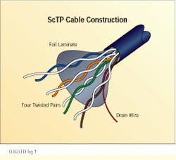
Three years ago, TIA opened project PN-3193 and chartered a task group to complete specifications on shielded 100-ohm cabling. One of the first actions of the group was to agree on a terminology--screened twisted-pair cable. Another was to limit the initial specification development to one cable configuration--four unshielded twisted-pairs with an overall foil-laminate shield and a drain wire.
The product of the three-year effort is a draft Telecommunications Systems Bulletin that will supplement the 568A standard and cover basic component and installation requirements for a shielded 100-ohm cabling installation. The ScTP specifications generally mirror the UTP requirements in 568A. Cables and connecting hardware are specified to the same Category 3, 4 and 5 limits on transmission performance. The connector interface is still the 8-position modular jack and plug, compatible with unshielded modular jacks and plugs. Cable color codes and connector pair assignments are also the same.
However, there are some differences:
-Because the shield can make the cable stiffer than UTP, the recommended minimum bend radius is 8 times the cable diameter (or approximately 2 inches) rather than 4 times the diameter currently allowed for UTP.
-Because the presence of a shield tends to require thicker conductor insulation to maintain the same impedance and attenuation specifications as UTP, 24 American Wire Gauge, or AWG, screened cord cannot be made to fit modular plugs of conventional configuration. It may be necessary, therefore, to allow 26 AWG ScTP cords as an option. The higher attenuation of 26 AWG cords will require a proportional adjustment in length, preferably done in the crossconnect patch cord or the equipment cord, where lengths are more easily controlled.
Where, and how often, do you ground a shielded system? Do you need full shield coverage over the entire cabling system? Is it necessary to maintain shield continuity throughout the system? All these questions were addressed by incorporating many of the shielding requirements that have been used successfully with 150-ohm STP since the mid-1980s. The 150-ohm shielding requirements start with the assumption that the shield will be grounded at each end.
The workstation end of a horizontal cable shield is normally grounded through the equipment connected to that end. Typically, this is done through a shielded equipment interface connector, where the shield is grounded directly to the equipment chassis and chassis ground. The draft TSB or other cabling standards do not control the equipment interface, so it is up to the user to ensure that any equipment or network interface cards used with a shielded cabling system provide such an interface and ground path. Most network interface cards already provide a shielded modular jack interface for 100-ohm cabling.
The proposed TSB requires the wiring closet end of the cable shield to be grounded to a telecommunications grounding bus that conforms to the TIA/EIA-607 standard on telecommunications grounding and bonding requirements. Typically, the cable shield is grounded through a connector to a patch panel, which is then grounded to a rack, which in turn, is grounded to the telecommunications grounding bus.
Ground-loop problems are avoided by requiring that the voltage potential and the resistance between the cable shield and the workstation power ground be measured and controlled within certain limits.
Grounding the shield at each end implies that the shield be continuous from end to end, which in turn, implies full coverage. The draft TSB, in fact, specifies that the system be fully shielded from end to end. The ISO/IEC 11801 standard requires that all cabling components be shielded, and that the shielding be continuous for the complete channel, including the work area equipment cables and equipment attachments that are not part of the generic cabling.
The issue of ensuring shield continuity through mated jacks and plugs was addressed first by surveying the various shield interface designs on the market. The survey confirmed that there were differences that, in combination, may not provide shield contact or enough contact wipe to clean off contaminants. Fortunately, most of the connector manufacturers were already members of the task group and agreed to change to a common set of parameters for their products. These parameters are incorporated as an interface requirement into the draft TSB.
The final frontier
The characterization of cable shielding performance has been straightforward using established test methods. That leaves the characterization of connecting-hardware shielding performance as the last major gap.
Unfortunately, connecting-hardware shielding performance cannot be specified until the task group finds or develops a suitable test method--one that can cover a 1- to 100-megahertz frequency range, be adapted to all configurations of connecting hardware and be independent of the cable. Fortunately, recent breakthroughs in gigahertz transverse electromagnetic cell and transfer impedance testing may provide the solution. With these new developments, the draft TSB may be completed by mid-1996.
However, the completion of the TSB may not mean the end of standards activity. The question of whether 100-ohm cables with individually shielded pairs will justify additional specifications on frequency range or performance still remains. Also, the electromagnetic compatibility needs of the channel must be defined and correlated to component characteristics. This item is already on TIA`s to-do list--and not just for shielded cabling. The electromagnetic compatibility for UTP depends on the balance of the cabling, which is also undefined.
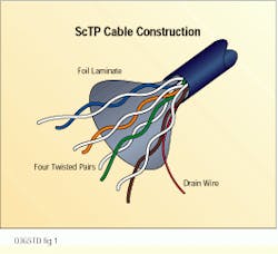
The basic construction of screened twisted-pair, or ScTP, cable includes four unshielded twisted-pairs with an overall foil-laminate shield and a drain wire.
Ned A. Sigmon, RCDD, is associate director of technical marketing for the Communication Products Division of AMP Inc., Winston-Salem, NC.

