Applications for 28-AWG twisted-pair cabling systems
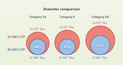
Most of the copper patch cords found in telecommunications rooms (TRs) today are constructed with 24-AWG copper conductors. With copper pairs of this size, a typical Category 5e cord is approximately 0.215 inches in outer diameter (OD); a typical Category 6 cord is 0.235 inches in OD; and a typical Category 6A cord is 0.275 inches in OD. By contrast, cords that use 28-AWG copper wires are significantly smaller in diameter. A Category 5e cord with 28-AWG wires is 0.149 inches in OD (48 percent the size of a typical Category 5e cord with 24-AWG wires); a Category 6 cord with 28-AWG wires is 0.15 inches in OD (41 percent the size of a typical 24-AWG Category 6 cord); and a Category 6A cord with 28-AWG wires is 0.185 inches in OD (45 percent the size of a typical 24-AWG 6A cord). In all these cases, the use of 28-AWG rather than 24-AWG wires reduces the cord's size by more than 50 percent. In this article I will detail the advantages that come with the use of 28-AWG cabling - in telecom rooms as well as in data centers - in addition to other considerations, to help you understand and decide if 28-AWG cabling is a good fit for your situation.
The use of 28-AWG cabling is exciting because it can be used immediately to help solve current TR and data center challenges. Downsized or otherwise small, crowded TRs are a reality for many users, as are congested pathways, insufficient space for new equipment, and the challenge of patching bulk when using high-density patch panels. The space within a TR or a data center is prime real estate because of its function and the concentration of equipment within it. But the copper patch cabling within a rack or between racks often drives how well users can meet the space challenges in these areas. For example, many times a rack has open space available that could house more equipment, but there is little or no room to effectively add the patch cabling that would be needed. In scenarios like this, the use of smaller, 28-AWG patch cabling can be a solution. As an aside, 28-AWG cabling can be used in other portions of the channel with many of the same benefits, but the focus of this article will be on patching within the TR or data center.
Drawn to proportion, these illustrations show the difference in outside diameter of Category 5e, 6, and 6A cables containing 24-AWG conductors (red) and those containing 28-AWG conductors (blue). In all cases, 28-AWG cables are less than half the size of 24-AWG cables.
Common patch cabling challenges include congestion that makes moves, adds and changes (MACs) a time-consuming endeavor, as well as the use of layouts that consume space in order to make it easier to work with patch cabling bulk - but do so at the expense of added equipment costs for horizontal managers along with less-than-optimal use of rack space. All these challenges drive up network costs in one way or another, such as higher operating expenses because of time-consuming MACs, or higher capital expenses from additional equipment costs. A goal, then, is to address these patch cabling challenges and in doing so, lower overall costs.
To understand why 28-AWG patch cabling has begun to be used fairly recently, it is worthwhile to look at a bit of history. Traditionally, a significant influence among designers, installers, and users of structured cabling systems has been the TIA-568 standard. Initially released 24 years ago, TIA-568 established the 100-meter maximum length for a copper cabling channel and also incorporated common cable sizes at the time, with 24-AWG cabling being typical. But it is widely known that telecom rooms and data centers have seen many new challenges since TIA-568's first publication in 1991, driven by new network capabilities. These capability-caused challenges have forced the industry to consider new ways to best solve the critical space issues within the prime real estate that is a TR or a data center.
Enter 28-AWG cabling. Not only is it significantly smaller than 24-AWG cabling, as previously detailed, but it can be used immediately in most common TR and data center scenarios to help solve space challenges by increasing pathway capacity, enabling higher-density layouts, facilitating easier cable management, and ultimately lowering costs as a result.
Enabling easier management
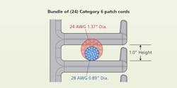
One example of the space and consequent money savings gained by using 28-AWG cabling can be seen in the use of a typical vertical cable manager, which has a finger opening of 1 inch. A 24-cord bundle of 24-AWG cords has a diameter of 1.37 inches - larger than the size of the finger opening, making such a bundle difficult to work with. In comparison, a 24-cord bundle of 28-AWG cords has a diameter of 0.89 inches. It easily fits into the 1-inch opening and technicians in the TR or the data center can readily work with it.
A bundle of 24 Category 6 patch cords with 24-AWG conductors is too large to fit through the 1-inch finger opening of vertical cable managers, while a bundle of 24 Cat 6 cords with 28-AWG conductors easily fits through the opening.
Looking at the pathway space within a typical 4-inch vertical cable manager, the advantages of 28-AWG are even more demonstrable. For this example, we'll assume we're working with Category 6 patch cords in a 4-inch manager, and using a 50-percent fill ratio, which is considered “full” for working capacity.
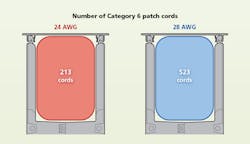
A typical 4-inch vertical manager can fit either 213 24-AWG cords or 523 28-AWG cords - translating to 146 percent more 28-gauge cords than 24-gauge cords. What would it mean to be able to more than double the capacity of your existing manager? For some of the telecom rooms we have seen, it would mean the ability to actually fit the patch cabling inside the manager and close the door. Remember, you get this capacity increase where you need it most, within the prime real estate of a TR or a data center.
At the patch panel, the use of 28-AWG cords results in more open space between the cords where they are plugged in. As illustrated in this article, the typical space between 24-AWG Category 6 parch cords very close to the patch panel is 0.315 inches. When you use 28-AWG Category 6 patch cords, the space opens up to 0.4 inches. It may not sound like a lot, but percentage-wise, it is 27 percent more open space between cords.
The benefits of this increased space between cords may not be self-evident, but consider the following.
- It means better port number visibility, especially on high-density panels.
- It also means easier cord management because there is space for fingers and plug access, as well as space for routing cords.
- Better airflow and equipment cooling - which are particularly important with large chassis switches - are also benefits.
- And it means new configurations are feasible. These configurations can include the use of fewer, or no, horizontal managers because of the ease of cable management. The use of high-density panels is more effective because the patching bulk is reduced. Even a layout like direct-switch patching, or port replication, is practical when 28-gauge cagling is used rather than 24-gauge.
A typical 4-inch-wide, 4.4-inch-deep vertical cable manager can accommodate 213 Category 6 cords, adhering to a 50-percent fill ratio, if those cords contain 24-AWG conductors. That same manager, still adhering to the 50-percent fill ratio, can accommodate 523 Category 6 cords that contain 28-AWG conductors.
Now let's take a step back and put all the pieces together in the example of a typical TR rack, to detail the benefits 28-AWG patch cords could provide when you face a change or expansion in the TR. For example, a user organization may acquire and move into new space, it may move a group of people within owned space, or it may need to install some new equipment. Any of these scenarios is an opportunity to use 28-AWG and realize its advantages.
Improving typical layouts
A very common two-rack TR configuration consists of one rack used for horizontal crossconnect and the other primarily used as a network rack, housing the switch and power source. This familiar scenario is a staple within large office TRs.
In this example, the crossconnect rack contains 9, 2-RU flat patch panels, each containing 48 ports. The rack also contains 10, 2-RU horizontal managers for a total of 38 rack units. The network rack contains 2, 2-RU horizontal managers; 1, 2-RU flat patch panel containing 48 ports; 1, 1-RU fiber tray; a Cisco Catalyst 6513 network switch, and 2, 3-RU power supplies. This equipment occupies a total of 33 rack units. In summary, 71 RU is used between the two racks to provide 480 ports, leaving 19 RU of available rack space. Looking closely at these numbers, we see that horizontal managers - commonly used to manage the mass of 24-AWG patch cables - account for more than a third of the rack space. We also see that the 480 ports (comprising 10, 48-port patch panels), require 20 rack units of space. Overall, this is relatively low rack utilization, with the patch cabling being a main reason for that low-utilization level.
Using 28-AWG patch cabling can help increase rack utilization and open more available space in the same rack layout. We will use the identical port count (480) and network equipment. On the crossconnect rack, the 28-AWG cabling allows us to effectively use high-density panels - 48 ports in 1 RU rather than in 2 RU - thereby cutting in half the RU needed for patch panels. So 9 RU, rather than 18 RU, are occupied by ports.
Importantly, we also can use angled rather than flat patch panels, because the 28-AWG cabling enables better port visibility and easier wire management. The use of angled patch panels, along with better visibility and easier management, eliminates the need to use horizontal managers to feed cords to each panel from above and below. Instead, we can use a single, 3-RU horizontal manager whose purpose is to get cords to the other side of the rack. Going from 10, 2-RU horizontal managers to a single, 3-RU horizontal manager saves 17 RU. So far we have saved 26 RU of rack space and 9 horizontal managers.
On the network rack, we save an additional 4 RU by using a high-density angled patch panel (saving 1 RU) and a single, 1-RU horizontal manager (saving 3 RU). In total then, between the two racks, we have saved 30 RU. That RU savings could be used for immediate expansion within the existing space, or as a more-compact footprint for future deployments.
Conserving that much rack space actually enables another option: Consolidating the existing crossconnect and network equipment onto a single rack. In this scenario, even the consolidated rack would have 5 RU of open space, because consolidating the horizontal managers saves 1 RU. Essentially, we gain a free rack for expansion space for new equipment, or handling cutover transition to a new switch. This setup also can be a solution when there is only enough space for a single rack.
In either of these scenarios, we have created available rack space for expansion within existing real estate, thereby avoiding the significant costs associated with expanding the rack footprint or the room size - which in many cases is not a realistic option anyway. In summary, the use of 28-AWG rather than 24-AWG patch cabling allows users to either put more into the existing TR footprint, or shrink the size of a future TR's footprint.
Another common TR or data center situation that 28-AWG cabling can help solve is the congestion of horizontal and vertical cable managers and the overall amount of patch cabling used. Here again, we can examine a typical two-rack layout. In this case the network rack has two 8-RU chassis switches (for redundancy), for a total of 768 ports and cords.
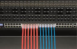
The red Category 6 cords on the left contain 24-AWG conductors, while the blue Category 6 cords on the rgight contain 28-AWG conductors. A blue cord's outer diameter is 0.15 inches in outer diameter, which is 41 percent of a red cord's 0.235-inch OD. This difference in size enables several cable-management advantages in telecom rooms and data centers. For example, and visible here, is the average space between two 24-AWG (red) cords is 0.315 inches, while the average space between two 28AWG (blue) cords opens up to 0.4 inches.
In the 24-AWG cabling scenario, all the cords are routed to the crossconnect rack via vertical and horizontal managers. It uses angled patch panels at a density of 36 ports per rack unit. In this layout, patching becomes dense. Furthermore, because of the cable-routing layout - driven by the bulk of the cable - several different cord lengths are needed; this fact increases the time required both to install the patch cabling initially and to manage it over time. Also, the physical layout of the cabling requires a significant amount of patch cabling. In this very common scenario, there is more than a mile of patch cordage in place.
When 28-AWG cords are used in this same situation, less space is occupied, bundle sizes are reduced, the use of high-density panels fitting 48 ports in 1 RU is accommodated, and horizontal managers are eliminated. Also, importantly, this setup allows a much-more-compact side-by-side layout that reduces the amount of cordage needed by 60 percent.
Reducing the amount of cabling required by 60 percent obviously saves material cost, while the simplified layout and cord lengths reduce operating costs because less time is required to install and maintain the system.
Suitable applications
With the examples cited, you may be wondering why not use 28-AWG patch cabling everywhere? There are some guidelines for use that can help identify suitable and potentially unsuitable applications for 28-AWG cabling.
One of the most common questions about 28-AWG cabling is whether or not it complies with TIA standards. The short answer is, “No.” The conductor size, 28-AWG, is outside the range specified in ANSI/TIA-568-C.2; that standard says: “Cord cable shall consist of four balanced twisted pairs of 22 AWG to 26 AWG thermoplastic insulated solid or stranded conductors enclosed by a thermoplastic jacket.” The “C” revision of the 568 standard was published in 2009, and interest in 28-AWG cabling has arisen much more recently.
Additionally, 28-AWG cabling does not support a full, 100-meter channel as specified in the 568 standard. For those reasons, 28-AWG cabling does not comply with the widely used ANSI/TIA-568-C.2 standard.
While I cannot speak for any other manufacturer's products, I can confirm that Panduit's 28-AWG cabling does comply with the 568-C standard's performance requirements, including near-end crosstalk and return loss, for patch cord tests or within a channel, when used within specific length guidelines. This can be compared to several in-field practices that are common today, such as home-run cabling using patch cords, or using stranded rather than solid cabling in the horizontal - neither of which are included in the standard but are commonly implemented.
In the case of Panduit's 28-AWG cords, they also pass the TIA's patch cord component tests, which we perform as part of the 100-percent factory testing of the cords we produce.
TIA-568-C specifies a maximum 100-meter length channel for copper cabling, which comprises 90 meters of permanent link cabling (typically solid cable) and a total of 10 meters of patch cabling. If you use 28-AWG patch cabling, you must adhere to a de-rating factor that reduces the maximum channel length achievable. Following are two common examples.
If your goal is to maintain the 90-meter permanent link, a total of 6 meters of 28-AWG patch cord can be used, for a 96-meter channel length. If your goal is to maintain 10 meters of total patch length, then the maximum permanent-link length must be adjusted to 83 meters, for a maximum channel length of 93 meters.
The shorter channel length is necessary because of the higher attenuation inherent in the 28-AWG cable's smaller wires. The necessary de-rating can be calculated using a straightforward formula.
PoE considerations
Another frequently asked question about 28-AWG cabling is its ability to support Power over Ethernet (PoE). PoE has been receiving increasing interest recently because new standards are in development and new applications are being supported by PoE. The good news is that 28-AWG patch cabling can support even the highest PoE levels being considered today. Not only the highest power levels available today, but also the highest power levels under consideration by standards-development bodies.
The one guideline to keep in mind concerning 28-AWG cabling and PoE is the number of cables that can be bundled together in order to stay within the recommended maximum 15-degree-Celsius temperature rise. The TIA's Telecommunications Systems Bulletin TSB-184 deals with PoE and cable-bundle sizes. In the latest version it references a maximum bundle size of 100 cables, which, as a practical matter, is most likely to be implemented as a 96-cable bundle, since 96 is a multiple of 24.
When using 28-AWG cabling, because of the cables' smaller size, more heat buildup can occur since the cables are closer together. To stay within the recommended temperature rise, the cables must be grouped in smaller-size bundles, such as 24 or 48 cables each. For current PoE implementations - 802.3af and 802.3at - up to 48, 28-AWG cables can be bundled together. With the expected high power levels to come in 802.3bt, up to 24, 28-AWG cables can be bundled together. As is the case with other references within this article, these bundle sizes of 48 or 24 cables refer to Panduit's own 28-AWG cabling products, and are based on testing we have performed on those products. For information on products from other suppliers, please refer to those suppliers.
Taking into consideration all the information contained in this article, we recommend the use of 28-AWG cabling, rather than 24-AWG cabling, in situations in which you are seeking relief from overcrowded pathways (such as existing applications), or need a higher density layout (such as in new configurations), and where a channel length slightly less than 100 meters is acceptable.
In situations in which the full 100-meter channel is needed, PoE or PoE Plus are being used with bundles of more than 48 cables, or where full compliance to TIA standards is required, 24-AWG cabling should be used.
The primary focus of this article has been on 28-AWG cable and its characteristics. However it is important to consider connectivity components like jacks and plugs, and their support for 28-AWG cable - especially if you plan to modify a cord in the field in any way, such as making an equipment cord, or shortening a cord by cutting it to length and putting a new plug on it. Because of 28-AWG's smaller wire gauge, jacks and plugs designed for 24-AWG almost certainly will not work and cannot be used with 28-AWG cable. Of course, a 28-AWG patch cord can be plugged into any standard RJ45 jack, regardless of the gauge of cable terminated to that jack. In fact, at this point nearly all 28-AWG patch cords are used in mixed-gauge channels where the permanent link and, in some cases, even patch cords on the channel's other end are not 28-AWG.
This is an exciting new area in copper patch cabling that can provide immediate help with current needs, like increasing pathway capacities, achieving higher-density layouts, easing cable management, and reducing both initial and ongoing costs in telecom rooms and data centers.
Thomas Baum is senior product manager with Panduit (www.panduit.com). This article is derived from a web seminar on the topic that Baum delivered in June 2015. That seminar will be available for on-demand viewing, until December 2015, at cablinginstall.com/webcasts.
