Cable tray systems support cables' journey through the data center

By Patrick McLaughlin
In the complex ecosystem of a data center, the support and distribution of communications cables between connection points is a minor consideration when compared to other networking and facilities characteristics like high-speed networking, network architectures, and of course thermal management. But because the data center is indeed an ecosystem and its elements are, to some extent, interdependent upon each other, the conveyance of cables throughout the facility commands thoughtful planning and execution. For professionals involved in the installation and routing of cables, their conveyance is a primary concern. This article explores some of the issues involved in cable conveyance, particularly with the use of cable tray as the form of conveyance.
In many cases, a data center contains a significant number of cables to accommodate the network’s high-volume, high-density connections. That being the case, we asked providers of cable tray systems what characteristics of a tray system enable it to support large volumes of cable that traverse a data center.
Patrick Keller, product manager for cable tray with Eaton, noted, “A wide range of widths and depths are available to allow for future expansion as the infrastructure grows.” Additionally, he said, a tray should provide easy access for the addition or removal of cables, as well as the ability to separate communications cables from power cables to minimize signal interference.
Snake Tray’s national sales manager Scott Jacobitti commented, “When we look at today’s modern data centers, the sheer volume of cable is mind-boggling. The old tired method of using standard steel runway is not necessarily the best choice for today’s advanced data centers. Runway is a flat, linear solution that requires cables to be bundled and secured to the structure due to the lack of a vertical containment component. A vertical element is extremely necessary to accommodate the high cable volume while still staying within the horizontal footprint of the cabinet rows. Basket-style cable trays offer the necessary vertical component, provide enhanced support for the cables, can be used for both power and data pathways, and can act as an EGC [equipment grounding conductor] when necessary.
“When exiting or entering the pathway, cable continuity and integrity is of utmost importance,” he continued. “Cable dropouts or waterfalls can be installed either along the side of the tray, inline or over the top rail of the basket tray allowing for smooth egress of the cables from the tray. Additionally, basket-style trays provide a more consistent supportive structure with a tight wire grid typically not exceeding a pitch of four inches. Cable runway typically uses 9- to 12-inch pitch between the ladder rungs, and therefore does not provide as much support for the cable.”
He added that it is “extremely important to make sure that all transitions are completed with sweeping arcs in order to maintain proper cable-bending radii. Simple butt-style turns, tees and crosses do not allow for the large numbers of cables to transit from one plane to the next unless there is a large-enough radii associated with the transition. Too tight a radius will compromise the capability of the cable to meet spec.”
In a technical paper titled “Shaping up pathways with shaped cable tray,” Chatsworth Products Inc. said, “In general, the best practice in network cabling applications is to ensure that pathways do not strain copper cable through sharp bends, twists or crimping that can change physical properties of the cable (i.e. twist rates and the relative positions of cable pairs). Ignoring this practice can result in a network that has to resend data, slower networks or the loss of a network connection.
“This risk is compounded in high-speed networks like data center networks where some connections are the critical connections between computer processors and computer data storage. Fiber cable, which has a glass core, has similar physical properties and concerns. Crimped fiber and sharp bends can result in unseen damage that causes the light signal to be lost.
“Hoping to reduce this risk with an update to traditional wire basket trays, Chatsworth Products Inc. is offering OnTrac Shaped Tray as an alternative design.”
While traditional cable-tray systems use a round crosswire to support cables, OnTrack Shaped Tray features flattened crosswires “that have been designed to increase contact surface and support,” Chatsworth explained. “This need for an increased contact surface is especially important in high-density applications, where even a moderately sized cable tray can hold in excess of 500 individual Category 6A UTP cables, leaving cables installed at the bottom of the tray to support the weight of several hundred sitting on top.”
Branches and arteries
The setup of many data centers-as well as enterprise networks-calls for numbers of cables to branch off from a main artery to smaller runs. Additionally, cables are fed from a tray to racks or cabinets housing computing equipment. Both Eaton and Snake Tray provide products that accommodate these types of transitions from “main” to “secondary” arteries as well as from tray to racks or cabinets.
“The tray system should be flexible enough to be adjusted on-site to avoid the many unforeseen obstructions under the raised floor or overhead, such as various products and equipment integrated into the same space required by different trades-HVAC, mechanical, security, et cetera,” said Eaton’s Keller. “Cable tray ‘drop-outs’ should be implemented into every design to ensure all cables maintain a proper bend radius as they are fed into racks, cabinets and other equipment within the data center. These ‘drop-outs’ help eliminate the concern of cable damage and performance degradation.”
Added Snake Tray’s Jacobitti: “Our 801 Series Mega Snake is a hybrid wire basket tray that offers the flexibility of basket tray and the strength and ease of installation of ladder tray. Maintaining the integrity of the cable plant while exiting or entering the tray is paramount in good data center design. The Mega Snake system offers many cable egress methods from either side of the tray or along the bottom of the tray. These waterfalls or cable ‘drop-outs,’ as they are more commonly known, provide complete support for the cables and maintain the proper bend radius for the cables as they move from the tray to the racks and/or cabinets.
“In the data center it is commonly required to reduce the tray sizes in areas where less cable volume is required,” he said. “Because of the modular design parameters, the 801 Series Mega Snake offers many types of reducing transitions that can be used to reduce the tray sizes. Both horizontal and vertical reductions are available and unlike generic basket tray, do not need to be field-fabricated. Field-fabricated transitions are very costly in labor budgets and can, in many cases, take as long as an hour to construct depending on the size of the tray in question. Also inherent to their design, generic wire basket trays are very difficult to maintain consistency in both electrical bonding and physical appearance since each one is its own erector set. Sharp edges are commonly found within these transitions due to the sheer volume of wire cuts, and by code need to be ground smooth-another huge time-consuming characteristic.
“The Mega Snake solution eliminates all of these issues by offering factory-built preconfigured transitions that are always consistent, have no sharp edges, and provide a completely bonded solution,” Jacobitti explained. “One of the aspects in any data center is consistency. As an agent for a colocation facility or any other data center facility, you want your customers to be able to feel safe. And that can start with the appearance of the infrastructure. Consistency is the key and the 801 Mega Snake cable tray solution provides just that sort of visual expression.”
Codes and standards
Complying with building codes as well as industry standards is always part of a cable-tray system design and implementation. We asked Keller and Jacobitti specifically about the cable-fill capacities within trays.
“Cable trays are covered in Article 392 within the National Electrical Code-NFPA 70-which is produced by the National Fire Protection Association,” Keller noted. “For cable trays that contain control and/or signal cables only, the sum of the cross-sectional areas of all cables at any cross section shall not exceed 50 percent of the interior cross-sectional area of the cable tray. This allows for the air gaps in between each of the cables. The maximum number of cables allowed within the cable tray is ultimately dictated by NEC requirements.”
Snake Tray’s Jacobitti added, “NEC and BICSI requirements for cable capacity are fairly consistent in that both require less than 100 percent of the tray be filled. Forty to fifty percent is what is commonly required; when the cables are installed in the tray to the prescribed percentages, one may say that the tray is at 100 percent.” He pointed out that codes and standards discuss a tray’s cross-sectional area, not its physical volume. “Open voids between cables will always be present due to the fact that the cables are round, not square. To that end, when the cable tray is at capacity per the code, visually we may see that it appears the tray is 100-percent full, depending on the density of the pack. The less-dense the pack, the fuller the tray will look.
“Cable manufacturers advise that cables be installed in a loose pack in order to minimize alien crosstalk. Tightly bundled cables are more prone to this phenomenon, since the twists of the cable have more opportunity to line up and allow for alien crosstalk,” he continued. “However, the code is the code-even if we pack the cable into dense bundles, the cross-sectional area is still the same. As an example, a 4-inch-deep, 12-inch-wide tray offers 48 square inches of cable pathway. Assuming the code requires a 50-percent fill rate as its maximum, only 24 square inches of cable can be installed. Installing cable with a 0.24-square-inch surface area, we can install 440 cables. Forty-eight square inches of total pathway divided by the surface area of the cables give us 880 cables, and 50 percent of that allows for 440 cables total. This is the same quantity of cable, whether it is in a tight bunch, or when installed in a loose fashion as suggested by cable manufacturers. Visually, the tray will look ‘full’ when cables are loosely installed. Larger trays, when applicable, can be installed to allow for expansion of the cable plant where necessary or for a less-full appearance.”
About its OnTrack Shaped Tray, Chatsworth noted, “The presence of [the tray’s] flattened wires produced more surface area and support than round crosswires. Further illuminated through testing and side-by-side comparisons, the flattened crosswire design was proven to supply cables with up to 400 percent more surface area than standard round crosswires. In turn, this added support promotes a reduction in cable strain by as much as 63 percent, ensuring that the conductors within each cable are optimized to perform as intended within any high-density networking application.”
Overhead versus underfloor
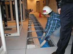
Whether cable conveyance takes place primarily overhead or underneath a raised floor is a decision that varies from facility to facility. Despite that variance, Snake Tray’s Jacobitti explains, “The pathway design in data centers is fairly consistent whether it is above the floor or under a raised floor. A common practice is to set out a grid in order to transmit cables from point A to B. This ‘street-and-avenue’ approach can be set on top of the cabinets or just below the surface of the floor tiles. Overhead tray solutions have a bit more leeway due to the fact that the overall space, in most cases, is open and free air space. Cooling is not impaired by the overhead cable tray and therefore can be routed in a more-direct fashion. Underfloor cable management does not have that kind of luxury, especially when the plenum air space under the floor is being used for data center cooling, and the fact that it needs to follow a 2-by-2-foot grid as laid out by the floor.
“It is imperative that the hot-aisle/cold-aisle configuration be maintained and not impede the cold air from reaching its destination. Under-floor cable management needs to maintain these channels in order to provide a direct cold-air delivery system. Cable trays are commonly stacked in the hot aisle and can become extremely dense in the capacity of the cable. When using a stacked approach, access to the lower trays should be taken into consideration by offering the use of narrow trays at the top and wider trays at the bottom. When designing these pathways, provisions for future growth and maintenance also need to be taken into consideration. The 301 Series Snake Canyon is a 2-by-2-foot modular tray solution for the raised floor environment, and can be deployed at multiple elevations underfloor, and fits within the grid pattern under the floor. Full-width and half-width trays are available and provide for the absolute maximum capacity for cables under the floor since there are no horizontal braces required for installation. The modular design also provides for simple and fast installation and can be installed within every floor.”
Overhead cable tray systems, on the other hand, are more apt to follow a more-direct route from one location to the next, because air handling concerns are not as much of a factor, Jacobitti continued. “Stacked solutions are also common in overhead installations, but accessibility is not impaired to the extent of that for under the raised floor. To this point, the need to have multiple-width stacked trays is in no way an accessibility issue; it would be more coupled to the cable capacity requirements. As the overhead installation is in free air, modifications to the design are easier to perform given that there are minimal impedances due to the lack of the floor grid, and in many cases, ample space surrounding the tray. Maintenance of the cable plant can be easier as well, since the technician does not need to lean over the edge of the floor, remove tiles or work in the very strict space constraint that is common in raised-floor environments.”
Patrick McLaughlin is our chief editor.

