The evolution of modular plugs and device end termination
By Yann Morvan, Legrand
Today most of the world follows ANSI/TIA-568 or ISO/IEC 11801 standards when it comes to structured cabling installations. Both standards were developed with the intent to support a range of current and future devices or applications that may appear in a building over an eight- to ten-year lifespan with permanent communication infrastructure. These standards have served the industry well, but they are now being challenged by modern technologies looking for faster, broader and more-permanent deployment within the building environment.
The exponential increase in wireless access points and IP-based cameras coupled with the proliferation of the Internet of Things and its related applications have encouraged installers and end users to revisit traditional cabling approaches intended to support these relatively permanent devices. New end devices, like Power over Ethernet (PoE) LED fixtures, are being considered fixed or permanent, therefore not requiring the same flexibility that the standards call for.
With these new technologies, we are witnessing the conversion of many commercial building devices and systems from analog, to digital, and now IP-addressable. The resulting migration of these devices and systems to four-twisted-pair cabling represents an additional class of equipment looking to be served by versions of communication cabling.
These market changes raise the question of whether these new types of devices are best served by: 1) existing structured cabling design, 2) modified structured cabling design, or 3) device-specific cabling to support new devices and systems.
Field termination of horizontal cabling
With the addition of these more-permanent fixtures and devices within the building, we are witnessing a growing demand for adding a plug directly onto the end of horizontal cabling without the use of a patching field, such as a consolidation point or surface-mount box. While the TIA-568 standards do not support this yet, the TIA is currently evaluating this practice and developing the appropriate testing methodologies.
The standards support plug termination onto horizontal cable, typically solid-conductor cable, only if it plugs into a modular consolidation point or onto cables coming from the back of a panel to plug into another panel. These kinds of methods are allowed because they comply with the channel and link guidelines and can also be tested as part of the final installed link or channel. Field termination on patch cords is also allowed because it can be tested to patch cord component specification.
The TIA TR-42.7 subcommittee currently is working on a normative annex to the TIA-568.2-D standard to include direct termination of horizontal cabling with a plug, also currently known as “modular plug terminated link” or MPTL within the standards discussions.
Different plugs
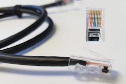
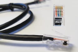
The most recognized field termination plug for four-pair cords is currently the eight-position modular plug, also known as the RJ45. They use insulation displacement contacts (IDC) that both terminate the conductors as well as provide the contact interface surface for the mating eight-position jack contacts. The IDCs extend from the inside of the plug where they pierce the wire insulation, contacting the internal copper conductors, to the outside where there is a smooth gold-plated surface that will mate with a jack. These plugs are crimp-terminated onto cordage or cable in a factory with field crimping tools. However, due to their termination method and pair arrangement (wires 3 and 6 are straddling 4 and 5), performance easily could be impacted.
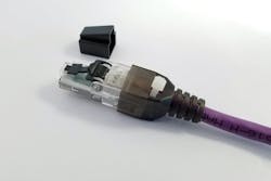
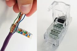
There is, however, a second type of eight-position modular plug that is designed to be more-easily terminated within the field and provide better performance control. This plug typically will use a termination method that is similar to a lacing cap termination found on modular jacks. This allows for the wiring position to be more easily viewed and managed within the field. When inserted into the plug, the copper conductors are pierced in the same manner as the standard RJ45 modular plug, but instead of interfacing directly with the gold contacts at the bottom of the plug, the IDC connects to a small printed circuit board (PCB) within the plug.
With an integrated PCB, the pairs can be terminated next to each other without crossover, avoiding potential user errors. The PCB also serves to eliminate noise sources that can be introduced with a plug termination.
The rise of IoT and new cabling
As discussed earlier, there is an increasing demand for direct plug termination of horizontal cabling for use with more permanently connected devices. We are seeing the emergence of LED lighting and other building systems being powered and controlled with PoE switches and twisted-pair cabling.
Some cable manufacturers have even built new cabling to support these specific applications. For example, Superior Essex’s PowerWise brand cable was built to reduce power loss that occurs within standard data communications cabling by using larger-gauge copper wires within the cable.
If a technician wanted to terminate the cable, which uses 22-AWG solid copper wires, with a plug, it would be very difficult to do with traditional modular plugs. While it is easier to manipulate the wires into straight lines with stranded wires, it is much more challenging to do so with solid wires. As a result, a plug using the lacing cap termination method as described earlier is recommended. This plug design allows for easier separation and placement of the wires while providing a more-reliable termination and overall performance each time thanks to the PCB.
The existing cabling standards are evolving to meet these new applications and it is important to take into consideration the impact of the modular plug on both the termination time and the performance of the overall system. With testing methodologies being developed and more IoT-based applications driving the need for plug termination of horizontal cabling, the market is set to move to adopting this new plug design at a faster rate.
Yann Morvan is director of product management at Legrand’s data communications division.


