What you need to know about direct attach connectors
By Tim Lehotsky, WSP
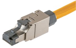
The structured cabling industry refers to a certain connector type as a “direct-attach plug” or “field-terminated plug.” Simply stated, it is a plug that is installed at the end of a horizontal cable, allowing the cable to be directly connected to an end device (think camera or wireless access point). On many occasions I have heard clients ask, “What do you mean I can’t crimp a connector on the end of a horizontal cable and plug it into my wireless access point?” Well, now you can.

This is Hubbell’s direct attach plug, which is available in Category 6 and Category 6A performance.
To clear up some possible confusion, let’s first discuss the use of the term “plug,” particularly as it is used in the structured cabling industry. Many people—and even some technical documents—will refer to the connector at the end of a patch cord as an “RJ-45 jack.” This article will not discuss why the term “RJ-45” is technically incorrect, but notice the use of the term “jack.” “Jack” is a commonly and broadly used term, but in our industry, the connector that is inserted into a patch panel jack, a wireless access point, or a computer’s network interface card is technically referred to as a plug.
So now that we understand why it is a field terminated plug and not a jack, what is wrong with a clear plastic plug you could buy from your favorite electronics store and crimp onto the end of a cable?
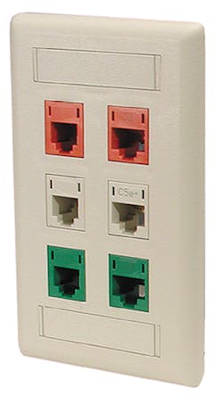
A typical outlet faceplate, like this one from Hubbell, will have an identification number for the entire outlet.
A while ago I helped a friend build a peer-to-peer network in his father’s office. I did the cabling (Category 5 at the time), and he installed the Novell Netware 3.12 (which should give you an idea of how long ago this was). I didn’t know a patch panel from a faceplate jack, from a J-hook. I crimped on RJ-45s at both ends. As we brought up each workstation, about half did not work. Not only did I learn what a link light does, I also learned how and why those connectors are a bad idea. Yes, I am certain there are technicians who are fantastic at installing these connectors, but there are inherent features of this connector that will always make them less reliable than that of a factory-installed connector. First, there’s no color coding on the connector, so you need to memorize the wiring pin-out. Second, if you don’t use enough compression the wires will pull out of the contacts or the sheath will pull out of the strain relief. Third, what may visually appear (and even initially tested) as a properly installed connector, may over time fail if tension is applied to the cable, thus loosening the strain relief and possibly dislodging the connections between the contacts in the connector and the twisted-pair cable. The new generation of field installed plugs described in this article offer improvements such as color-coding, 110-style insulation displacement termination of conductors, and improved cable strain relief.
Where do we use it?
If you read the literature from the manufacturers, you will notice that many still recommend the traditional jack and patch panel termination method. However, they do recognize the practicality and simplified installation of using this type of termination hardware. It is also worth pointing out that the standards bodies now recognize their use and there are conventional testing methods to certify their installation. Additionally the manufacturers will tell you these are not a cost-effective way to produce patch cords; their use is intended for the edge device connection, not inside the telecom room (for example from patch panel to switch). Some of the common, non-end-user applications where they are well-suited include the following.
- IP surveillance cameras
- Wireless access points
- Room schedulers
- Audiovisual cameras
- IPTV
- HDBase-T
- PoE lighting
- IP-enabled sensors
Why do we use it?
Some of these examples will be obvious to those who have installed these devices, but for others who see the device only after it is installed, the benefits of the connector may be less obvious. Sometimes an end device (in this example a camera or a room scheduler) will mount directly onto the electrical box that is installed within the wall cavity and has threaded holes that end device will fasten to. In a scenario such as this, it is not practical to install a conventional wall outlet faceplate and jack because this would conceal the threaded holes inside the back box and prevent the end device from mounting to it. Furthermore, even if there had been a way to anchor the device on top of the faceplate, there would likely be insufficient space to install a short patch cord between the jack in the faceplate and the port in the end device. It is in this type of example where the direct attached plug becomes practical, and advantageous. Here, a direct attached plug could be installed at the end of the horizontal cable and be neatly coiled inside the back box, so that it may be pulled out, connected to the end device, and then the end device may be anchored to the back box. (Note: If you do plan to coil a connectorized cable inside a back box, be certain to factor in the length of the connector and the bend radius of the cable.) Here, the use of a direct attach plug greatly simplifies the installation of the structured cabling systems.
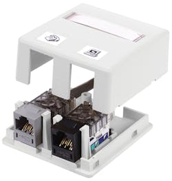
A ceiling outlet assembly with one or two ports—sometimes called a biscuit box—is commonly used to support a wireless access point. The use of a field terminated plug allows for the exclusion of such a device.
The room scheduler device at times may create additional challenges. We are seeing more and more of these devices; it is a tiny touchscreen device that will show if a conference room is in use and may allow someone to reserve the room. It is common to find these devices surface-mounted on the vertical metal framing (mullion) that separates glass panes when the conference room has a glass wall. In this scenario, it is not possible to install an electrical box, as there is no wall cavity, it’s just glass and framing. In the past, a standards-compliant structured cabling installation would dictate a ceiling outlet and a patch cord that was installed inside the mullion. With the use of the field termination plug, that ceiling outlet can be omitted.
Another example is an 802.11 wireless access point. These are often supported by the grid used for acoustical tile ceiling (some wireless access point devices will ship with these clips). The conventional design we often see is a small, plastic, plenum-rated box (sometimes called a biscuit box) with one or two jacks; this will be installed above the ceiling system and suspended from a J-hook. This assembly is more complex than you might think (two-piece plastic box, jack, labels, etc.), especially when compared to the simplicity of a horizontal cable with a field termination plug. The use of the field terminated plug allows for the exclusion of a “biscuit box outlet” and provides a simpler installation.
With Ethernet continuing to dominate as the LAN standard for wired networks and the proliferation of smart building sensors and other Internet of Things (IoT) devices, we expect to see increasing demand for the field terminated plug.
Providers and specifications
Field terminated plugs were, initially, slow to come to market due to concerns over how to test their installation. However, new designs and evolving test procedures have resolved such issues, kick-starting their introduction to the market. At the time this document was being written, at least one manufacturer announced the introduction of a field terminated plug. We expect that by the time of publication in June 2018, additional manufacturers will introduce products. The field terminated plugs included in this article are those we are familiar with and have worked with. The information in the tables comes directly from data sheets and other literature produced by these manufacturers. Plugs from other manufacturers also are available.
TABLE 1. | ||||
Manufacturer | Category 6 | Category 6A | ||
UTP | STP | UTP | STP | |
Belden | RVAF-PUBK-S1 | |||
CommScope | 760235591 | |||
Hubbell | SP6 | SP6 | SP6A | SP6A |
Leviton | 6APLG-S6A | 6APLG-S6A | ||
OCC | OCCUFP6A | OCCS-FP6A | ||
Ortronics Legrand | OR-FTPU-C6A | |||
Panduit | FP6X-88MTG | |||
Not every connector is compatible with every type of cable. Some work only with solid conductors, while others will also work with stranded conductors. Each manufacturer has a range of conductor sizes and cable outside diameters they will support. Some make a field terminated plug that is compatible with both shielded and unshielded twisted-pair cable. It is also important to point out that not all of the plugs are plenum-rated. Additionally, consider the manufacturer’s extended warranty if that is applicable to your installation.
TABLE 2. | ||||
Manufacturer | Cable sheath outer diameter (inches) | Individual conductor sizes (AWG) | Solid/Stranded/Both | Shielded cable |
Belden | N/A | N/A | N/A | No |
CommScope | All CommScope cables | 22-26 | Both | No |
Hubbell | 0.236-0.315 | 23-26 | Solid | Yes |
Leviton | 0.240-0.310 | 22-26 | Both | Yes |
OCC | 0.216-0.335 | 22-24 | N/A | Yes |
Ortronics Legrand | N/A | 22-26 (stranded) 23-27 (solid) | Both | No |
Panduit | 0.200-0.330 | 22-26 | Both | No |
The process for terminating the cable onto these connectors varies from manufacturer to manufacturer. Surprisingly, none of the connectors we evaluated use 110-style termination hardware. A few use tools specifically made for their termination hardware, and in both those cases, the same tool would be used for terminating other connectors from the same manufacturer. Multiple manufacturers require the use of flush cutters and/or parallel jaw pliers.
TABLE 3. | ||||
Manufacturer | 110-style punchdown tool | Flush cutters | Parallel jaw pliers | Proprietary tool |
Belden | No | No | No | Yes |
CommScope | No | Yes | Yes | No |
Hubbell | No | Yes | No | No |
Leviton | No | Yes | No | No |
OCC | No | Yes | Yes | No |
Ortronics Legrand | No | Yes | Yes | No |
Panduit | No | Yes | Yes | Yes |
Table 4 compares the physical sizes of the plugs. At least two things should be considered when evaluating a direct attach plug when it comes to its physical size. First, if the connector will be installed on a cable and then stored inside an electrical box, look at the overall length of the connector (including the dust cap, if available) and the required bend radius of the cable it is connected to. Second, look at the spacing between ports to confirm that two plugs will fit if they are seated in adjacent ports (for example a wireless access point with multiple Ethernet ports).
TABLE 4. | |||
Manufacturer | Width | Height | Length (Dimension C) |
Belden | 1.1 | 0.73 | 1.81 |
CommScope | N/A | N/A | N/A |
Hubbell | 0.56 | 0.62 | 1.74 |
Leviton | 0.54 | 0.6 | 1.59 |
OCC | 0.54 | 0.65 | 1.74 |
Ortronics Legrand | 0.55 | 0.5 | 1.79 |
Panduit | 0.53 | 0.62 | 1.82 |
Ratings, listings, PoE
These connectors are listed for use within a certain temperature range. Temperature rating may be a critical consideration when field terminated plugs are installed within a ceiling return air plenum or mechanical space. Additionally, a plenum-rated plug is needed when installing within a plenum environment and not all connectors are plenum-rated. Some manufacturers list the number of mating cycles and the number of times a plug may be reterminated and still meet the performance criteria.
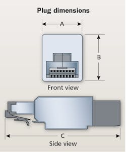
Direct attach plugs differ in widths, heights and lengths from manufacturer to manufacturer.
An IP rating is defined by standard IEC 60529. It classifies the degrees of protection provided against the intrusion of solid objects (including body parts like hands and fingers), such as dust, accidental contact, and water. An IP rating of 20 represents protection from fingers and solid objects greater than 12.5 mm, but carries no protection from the ingress of water.
TABLE 5. | |||||
Manufacturer | Temperature rating (deg. C) | Plenum rated? | UL listings | Front mating cycles | Reterminating cycles |
Belden | N/A | Yes | 1863, 2043 | 750 | 20 |
CommScope | -10 to +60 | Yes | 1863, 2043 | N/A | 20 |
Hubbell | N/A | No | N/A | N/A | |
Leviton | N/A | Yes | 1863, 2043 | N/A | N/A |
OCC | -40 to +70 | N/A | 1863 | 750 | N/A |
Ortronics Legrand | -40 to +75 | No | 1863 | N/A | 5 |
Panduit | -10 to +65 | Yes | 1863, 2043 | 2500 | 20 |
Power over Ethernet or PoE could be a topic of an article all by itself. If you go back and look at the list of devices that we expect these types of connectors to be used you’ll notice they are nearly all PoE devices. The IEEE PoE standards are evolving (IEEE 802.3af, 802.3at, 802.3bt). Manufacturers list their PoE compatibility in different ways—some in terms of what standard the connector is compatible with, others simply by listing a maximum power in watts. Table 6 includes PoE compatibility information taken directly from the manufacturers’ respective data sheets.
TABLE 6. | ||
Manufacturer | PoE compatibility (by standard) | PoE compatibility (in watts) |
Belden | 100 | |
CommScope | IEEE 802.3af, 802.3at and proposed 802.3bt | |
Hubbell | Proposed IEEE 802.3bt, Type 3 and 4 | |
Leviton | 100 | |
OCC | IEEE 802.3at | |
Ortronics Legrand | 100 | |
Panduit | IEEE 802.3af, 802.3at, and proposed 802.3bt Type 3 and 4 | |
Other features and concerns
Earlier we discussed some of these plugs’ technical specifications. Some manufacturers have included other noteworthy features that are worth mentioning, including color options, dust protection caps, and extended release hatches.
You also should consider some other features when reviewing your options. T568B is the dominant conductor pinout assignment for jacks and plugs. However, in cases where wiring standard T568A is used that may present a challenge because not all plugs we looked at are compatible with both T568A and T568B.
Additionally, there is also a variety of ways these plugs provide strain relief; some use a simple tie-wrap, others use compression where the cable is compressed by two parallel pieces of material. Some even use a form of compression that appears to uniformly compress the perimeter of the cable.
Finally, we pointed out earlier that some manufacturers identified how many times their field terminated plug may be reused, but we found that while some manufacturers do not specifically identify how many times their plug may be reterminated, they do state in their product literature that they may be reused.
Labeling and identification will continue to necessitate some creativity with regards to field terminated plugs. An outlet faceplate will often have an identification number for the entire outlet (e.g. 7A-101: floor 7, telecom room A, outlet 101). While many applications for the field terminated plug may consist of only one terminated cable, consider the application where there may be multiple cables. Multiple cables, terminated on jacks set in a faceplate, are easy to organize and identify as well as label in compliance with TIA 606 standards. However, two or more cables with field terminated plugs, coiled in a ceiling, suspended from a J-hook, are not grouped by a faceplate. Short of using two different colored horizontal cables, clearly distinguishing between the two cables will take some forethought. This is not a problem that cannot be overcome, just something to point out. If the field termination plugs were available in multiple colors, this would help.
TABLE 7. | ||||||
Manufacturer | Multiple colors | Dust cap | Extended release hatch | Strain relief | Wiring standard | May be reused? |
Belden | N/A | N/A | N/A | Compression | T568A, T568B | N/A |
CommScope | Yes black, white | N/A | N/A | Tie wrap | N/A | Yes |
Hubbell | N/A | Yes | Yes | Cylindrical compression | T568A, T568B | Yes |
Leviton | N/A | N/A | Yes | Cylindrical compression | T568A, T568B | Yes |
OCC | N/A | Yes | Yes | Cylindrical compression | N/A | N/A |
Ortronics Legrand | Yes clear, black, blue | Yes | Yes | Tie wrap | T568A, T568B | Yes |
Panduit | N/A | Yes | Yes | Compression | T568A, T568B | Yes |
Dust infiltration during installation is another concern. Often these cables will be installed and tested and then left to sit while the rest of the construction is completed. This may mean that plugs installed on cables either suspended in the ceiling or coiled inside an electrical box are exposed to particulates. Protecting the metal contacts from dust is an immediate worry. Some manufacturers include a dust cap that has a snug fit, however will remain attached if the connector get jarred. Perhaps a dust cap with a tethered connection to the jack, similar to the caps that are often found on individual connectors, would be a good improvement.
Warranty is another consideration, particularly if you plan to use a connector from a manufacturer that differs from that of the rest of the structured cabling system. Many manufacturers offer a 25-year or lifetime performance warranty. The introduction of another manufacturer’s connector may present a complication.
Testing
The ANSI/TIA-568 series is one of the dominant structured cabling standards, with the current version being ANSI/TIA-568-C.2. Currently the direct attached plug is not recognized by this version of the standard, which requires that a horizontal cable be terminated onto a modular jack at the work area to provide flexible access to the user. This flexible access is provided by the use of a work area patch cord. The absence of the field terminated plug in the current 568-C.2 standard has up until now led to challenges when it comes to testing. Recent innovations by the structured cabling manufacturers have largely reduced these challenges.
Structured cabling system are tested to validate that the installation complies with the performance requirement of the cable and connectors. When horizontal cables are certified they are often tested using the configuration prescribed in the standard, defined as the permanent link. Simply stated, this test method does not incorporate the patch cord at the work area outlet and the patch cord in the telecom room. Traditional test equipment setup will include a field tester main unit at one end of the link, and a remote unit at the other end. This permanent link is depicted in the diagram.
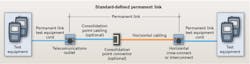
The ANSI/TIA-568-C.2 standard, which defines the permanent link, does not recognize the direct attach plug. Rather, the “C.2” standard requires that a horizontal cable is terminated onto a modular jack at the work area to provide flexible access to the user.
The test equipment is connected to the horizontal cable with permanent link adapter test cables at both ends of the horizontal cable. The test equipment is calibrated to exclude any performance data measured in the link adapter test cables. This presents a problem when field terminated plugs are introduced. If the field terminated plug is connected directly into the test equipment, the test results will not be accurate. Most manufacturers have published documents prescribing the test procedures. At least one manufacturer has provided their own permanent link test adapter cable. The test equipment manufacturers also have provided instructions on how to certify these connectors. As a result, an effective means of testing direct attach plugs, that yields accurate test results, has been made readily available.
Much of this has been incorporated into the soon-to-be ratified ANSI/TIA-568.2-D standard. A number of other manufacturers also have begun to produce their own adapter cables and test documentation to simplify the testing process.
What about standards?
As previously stated, the current ANSI/TIA-568-C.2 standard does not recognize the field terminated plug. Instead, it requires that a horizontal cable be terminated on a telecommunications outlet to provide flexible access to the user.
There are current standards (such as ANSI/TIA-862-B.1) that do currently recognize the use of field terminated plugs. This should provide some peace of mind and confidence to those designers and end users who want to deploy them today.
However, good news for the industry came last year when the TIA TR-42.7 subcommittee agreed to include field terminated modular plug (referred to as modular plug terminated links) within its normative annex. This will be incorporated into the ANSI/TIA-568.2-D, currently in draft status.
It is common in the telecommunications industry for either the manufacturers or the construction community to develop a new product or installation method that becomes a viable installation practice before it is adopted by the standards organization. The direct attach plug is another example of this.
The opportunities to deploy a field terminated plug are plentiful. Earlier we discussed the obvious ones—WiFi access points, room schedulers, surveillance cameras and others. One other interesting application we learned from one manufacturer is using the field terminated plug at the consolidation point. The consolidation point, as defined by ANSI/TIA-568, must be a mated connection, which makes the use of field terminated plugs ideal. With the proliferation of IP-enabled devices, we expect to see new uses develop.
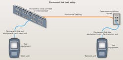
A permanent link test setup is shown here. The test equipment is calibrated to exclude any performance data measured in the link adapter test cables, which presents a challenge when field terminated plugs are introduced. Most manufacturers have published documents that prescribe test procedures for connections made using their field terminated plugs.
As with any new technology, caution should be exercised when a new connector is first introduced. We learned from one manufacturer, while the installation process is not complex, failure to follow the manufacturer’s instructions may introduce transmission failures and increase labor to correct the errors.
It probably hasn’t surprised anyone that the standards bodies have now accepted these connectors and are in the process of formally recognizing them. Additionally, concerns over how to test field terminated plugs have been addressed, making their effective deployment easier. As a result we expect to see field terminated plug use in the industry become common. As we have pointed out, there are some areas where we would like to see some improvements (color coding, dust/physical protection, administration), but nonetheless we are excited to see the field terminated plug become a viable alternative to traditional construction methods.
Tim Lehotsky is vice president of building technology systems for WSP USA (wsp.com). WSP USA, formerly WSP Parsons Brinckerhoff, is the United States operating company of the global engineering and professional services firm WSP.

