The evolution of hybrid fiber cable applications


Originally deployed in the campus backbone, fiber has become the dominant media choice for building backbone cabling due to increased data rates. And, as bandwidth requirements for connected devices increase, fiber is being deployed in the horizontal section of private networks, as well. One solution that is enabling fiber to run deeper into the network is the hybrid fiber cable.
From telephony to the modern network
As we look at the role that hybrid cable plays in today’s enterprise environment, we need to review the history of connected devices and the historical advantages of copper cabling. Wait, you might say. This is an article about the use of fiber optic cabling. But copper is still relevant as we look at data and powering of connected devices.
Since the beginning of the “network”, which goes back to the invention of the telephone in the 19th century, the challenge has been to balance power delivery, bandwidth and distance. Telephones at different locations were connected with a dedicated pair of wires between the devices. If a user wanted to communicate with another location, a separate telephone was installed for connectivity to that location. The next evolution of the network was the introduction of the Central Exchange, which allowed the routing of a particular telephone to be manually changed to connect to a different far end telephone.
It is interesting to note that the original telephones were powered by batteries in the handsets. As telephones became more widely used by the general population, those batteries quickly became a maintenance headache. So, in the 1930s, Telephone Exchanges began providing power remotely to the handset over the wiring.
During the late 1980s, the first structured cabling emerged with StarLAN-1 (IEEE 802.3e) defining the hierarchical star topology still used today, and 10Base-T (IEEE 802.3i) predicated on Category 3 cable (TIA-568-B). These original networking protocols only addressed the data connectivity, as the connected computing devices were independently powered.
Regarding voice communication, the separation of power and signal came in 1991 when the first Voice over IP (VoIP) networks were introduced as a desktop-to-desktop application. In early VoIP networks if local power was interrupted, the VoIP application would go down.
Remotely powered VoIP handsets were introduced in 1999, using proprietary powering over the data cable. This was the predecessor to standardizing the transmission of Power over Ethernet (PoE). In 2003, IEEE 802.3af was published, delivering 12.95 watts to the Powered Device (PD). The most recent update to IEEE 802.3 covers 71 watts PoE at the PD.
While switches, servers and workstations are not currently being powered over the network cabling, many other devices are taking advantage of PoE capability. Today’s networks include PoE PD’s such as cameras, Wireless Access Points (WAP), and telephones. Additionally, there are new operational technology (OT) devices, including access controls, temperature and motion sensors, and monitoring and control systems for building automation systems.
The best applications of copper cabling
As newer IT and OT devices join the network, power availability becomes a main consideration. Copper excels at delivering both power and data to these devices. Additionally, today’s enterprise networks are designed with multiple floor distributors (FD), such that all of the connected devices lie within the 100-meter channel limit defined in the TIA-568 standard. In other words, copper cabling provides for a very good balance of bandwidth, power and distance in the horizontal segment of the network.
When bandwidth requirements reach beyond 10 Gbits/sec, copper becomes less than optimal. WAPs conforming to the latest 802.11 standards only require connectivity up to 10 Gbits/sec. However, this may become an issue with next generation of the standard. For now, the majority of connected devices are adequately covered with copper bandwidth capabilities. However, the WAPs will likely require fiber connectivity in the near future.
Another benefit to using copper is the availability and simplicity of connectivity. End devices typically have RJ-45 ports, which are very common and often less expensive than fiber interfaces. Attaching the connector or plug to cabling is less complicated than terminating fiber connectors.
While copper is generally easier to terminate, there have been a lot of advancements in fiber termination technology. Fusion splicing, for example, provides a high-quality connection with low loss. Additionally, fusion splicers are more affordable than ever. And new products, such as fusion splice-on connectors are becoming more common, providing improved protection for the fusion splice joint, as it is included in the body of the connector.
Where does fiber cable fit in the network?
Fiber is commonly used in the campus and building backbone segments of the network. The campus backbone is the segment where a campus distributor (CD) connects to individual building distributors (BD) across the campus. The building backbone connects the BD to the FD within the building. These distances are typically longer than the horizontal segment of the network.
Generally speaking, the backbone is the segment of the network where traffic is aggregated to communicate upstream and downstream. As such, bandwidth requirements for this segment have increased.
What type of fiber should you deploy?
Should you use multimode or singlemode fiber in your network? The easy answer is to use multimode fiber when possible and singlemode when necessary.
Let’s explore the thinking behind that statement. From a cost perspective, for increased data rates, multimode transceivers still provide a cost benefit when compared to singlemode transceivers. Multimode fiber may also have advantages in the cost of connectivity and its tolerance to dirt and debris.
Within a building backbone, it is important to consider the distance requirements. For lengths up to 300 meters, multimode fiber can support speeds up to 100 Gbits/sec. This ability to support very high data rates over relatively long distances has extended the life of multimode fiber because it can still handle many backbone building requirements. The campus backbone typically presents more of a distance challenge. With lengths exceeding 300 meters, it is likely necessary to choose singlemode to reach speeds beyond 1 Gbit/sec.
Ultimately, the media choice depends on the size of the building. A small one- or two-story building might be able to accommodate copper in the building backbone. A very large building or a campus environment, might require multimode or singlemode fiber.
Fiber offers more than distance and data rate
Another advantage of transitioning from copper to fiber is lower maintenance costs. Optical fiber cables are extremely robust, protecting against physical stresses, such as tension, compression and crushing; and environmental stresses, such as heating, freezing or moisture ingress. The optical fibers have also been improved to accommodate tighter bends without significant signal loss. As such, even if the cable jacket is breached and some moisture gets inside that cable, the fiber’s performance should not be impacted.
Fiber is also immune to electromagnetic interference (EMI). Network operators do not have to worry about proximity to other EMI sources, such as electrical power transmission, ignition systems, cellular networks or environmental issues such as lightning or solar flares.
Optical fiber cable uses the space available in pathways more efficiently, taking up significantly less space than copper.
Finally, optical cable offers significant security advantages over copper. It is more difficult to tap the signal in a fiber cable without being detected.
Moving from the backbone to the horizontal
If optical cable offers lower maintenance costs, greater reliability, better EMI immunity and higher security, why does copper still dominate the horizontal?
So far, efforts to bring fiber closer to the user within a building have fallen short.
In 1996, TIA-TSB-72 introduced a concept called Centralized Optical Fiber Cabling. This approach eliminated the horizontal segment in the network, centralizing all equipment in the main equipment room. Fiber would run directly to all the device locations. Keep in mind, in 1996 the network was composed of telephony and workstations, with telephony running on a separate POTS network. As such, workstation connectivity meant running a limited amount of fiber to the device locations. This design was not cost prohibitive, but it was not very scalable, as it meant running additional cable back to the main equipment room to support new devices.
In 2003, the next architecture proposed to bring fiber deeper into the network was Fiber to the Enclosure (FTTE). This differed from Centralized Optical Fiber Cabling in that the telecom rooms would be replaced with telecom enclosures, which would be located closer to the end devices. FTTE is like a traditional network, except the backbone to horizontal transition is moved closer to the end user. In terms of initial installed cost, FTTE is cost neutral or a slight premium relative to copper. Looking at the total cost of ownership, the fiber provides future-proofing because it has much higher bandwidth than copper. Thus, as networking speeds increase, they can be more easily accommodated with an FTTE-type deployment. However, implementation of FTTE architecture did not take off.
The newest architecture to push fiber deeper into the network adopts the model used by the Service Providers to bring fiber closer to the subscriber: Passive Optical Networks (PONs). PONs create an infrastructure that delivers signal to thousands of locations, while minimizing the amount of fiber deployed.
The International Telecommunication Union (ITU) PON standards were developed in 2003 to support Fiber-to-the-Home (FTTH) deployments. The original Gigabit-capable Passive Optical Network (GPON) standard, ITU G.984, was an asymmetrical protocol addressing 2.5 Gbps download speed, and 1.25 Gbps upload speed. This asymmetry, with faster download speeds than upload speeds, worked fine when subscribers were mostly downloading content. But corporate networks require the ability to quickly upload large files as well. In the corporate environment, many networks have significant content that is not stored locally on the workstation. This makes symmetry much more important. In 2004, IEEE developed the 802.3ah standard, which addressed symmetrical network speeds of 1.25 Gbps.
The difference between the ITU and IEEE PON standards is relatively minor to the end user. The ITU standard uses a different encapsulation method to transport Ethernet packets. This allows for different types of packets, such as voice and video, to be transported, as well. The IEEE is a native Ethernet format. When using the IEEE PON, voice and video must be converted to, or encapsulated within, an Ethernet signal.
IEEE and ITU have continued to develop standards for higher network speeds. In 2018, IEEE published 802.3ca, which addresses symmetrical 25 Gbps capability. The current ITU standard, G.9807.1: XGS-PON, was published in 2016 and provides symmetrical 10 Gbps communication.
One of the advantages that PON offers in building design is the ability to eliminate TRs on individual floors. Space is at a premium in buildings and architects would benefit from eliminating these spaces, as they require power conditioning, power back-up and air conditioning. With all that’s involved, a TR can cost around $25,000 for initial construction. This is an obvious cost reduction easily achieved when deploying a PON.
However, one challenge present in PON is power availability. In the majority of PON deployments, the ONU/ONT located at the user work area is powered locally. As such, when local power is lost, the user will lose telephone service unless batteries are used for back-up power.
Barriers to implementing fiber deep architectures
So far, this article has discussed the advantages of fiber deep architectures, such as higher bandwidth, better immunity, better security, and being more mechanically robust than copper.
So why hasn’t fiber taken over the world? There are some practical and economic reasons to consider. For example, fiber interfaces are typically only found on higher bandwidth devices, such as switches and servers. But that does not represent the majority of devices that are deployed, which still have copper interfaces.
One of the more subtle barriers is “resistance to change.” Copper and hierarchical star topologies are familiar. Change is difficult. In general, network designers are comfortable with fiber in backbones, but they are more reserved when considering changes to horizontal design, or eliminating the horizontal segment, altogether.
Perhaps the biggest implementation barrier to fiber is the proliferation of new Information Technology (IT) and Operational Technology (OT) devices that require power. Building managers do not want to maintain a separate power and data grid for those devices. While many of these devices can be battery powered, that is a less than an ideal solution. Even though some batteries last a long time, when a building deploys thousands of IT and OT devices, the maintenance schedule to keep those batteries working would be a nightmare effort. As a result, Power over Ethernet (PoE) is one of the major things that is keeping copper in the horizontal.
Are hybrid cables the answer?
In hybrid cables, the fiber transports data and the copper accommodates low voltage power transmission. The fiber can be singlemode or multimode, depending on the application. The conductor sizes in these hybrid cables range from 20 AWG to 12 AWG.
By delivering DC power via the copper conductors, the typical AC-DC conversion inefficiency is eliminated. Additionally, if the DC power is limited to NEC Class 2 power, these cables can share the same pathways as data cables, eliminating the need for conduit in some situations. Additionally, a licensed electrician is not required to install a Class 2 circuit.
Class 2 power is delivered to these hybrid cables from the main equipment room using a modular, scalable SPS bulk rectifier shelf fed with AC power. The Power Express distribution shelf provides up to 32 channels to feed the hybrid cables, and each output circuit is separately controlled to ensure operation within NEC Class 2 limits. Incorporating the power supply unit in the equipment room simplifies power back-up to the end devices.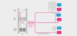
In terms of device connectivity, the cable can terminate to a surface mount box or directly to the end device. Some devices can accept the 48-volt power connection as well as a fiber connection via SFP transceiver. Alternately, a PoE circuit can be used to connect to a more traditional device, via a media converter or a PoE extender.
An example of a PoE Extender is shown in the figure. This device is IP-68 rated and designed for use in the outside plant environment. It has robust power conditioning and electrical protection to address inherent issues when running power outdoors. The PoE Extender also includes a DC-to-DC voltage converter to facilitate support of extended reach.
In situations where an outdoor device has an SFP input, a Power Extender can be used to address the power requirements for extended reach, while fiber is used for device connectivity.
Extended reach is driven by device power requirements. As an example, a device requiring 802.3af power (15W at PSE) could have a channel length of 3000 meters. With 802.3at power (30W at PSE), device reach is over 1500 meters. And, for 802.3bt, Type 3 power (60W at PSE), the distance can be more than 800 meters. For indoor deployments that do not require voltage conditioning, reach can exceed 450 meters for 802.3bt Type 3 powered devices.
Hybrid cables in action
Here are a couple of examples of how hybrid cables can support different applications efficiently and cost effectively.
Example 1: A university project involved deployment of 2,000 WAPs and security cameras in common outdoor areas. The hybrid cable and PoE Extender solution enabled the support of those devices from a minimum number of telecom rooms. By providing a power backup to the power supply in the equipment rooms, there was no need for local power backup for those individual devices. In this example, the DC power supply that was used had remote management capability. As such, network operators could power cycle individual outputs to potentially correct network connectivity issues without having to dispatch a technician.
Example 2: An airport project involved deployment of 32 security cameras on the airport terminal roof to provide security on the tarmac. Because the main user of this system was not the airport, network separation from airport assets was desired. The original design involved multiple air-conditioned enclosures on the roof top. Instead, with the extended reach hybrid cable, all cameras were connected to a limited number of IDF locations inside the airport. Again, the extended distance provided by hybrid fiber cable solutions made this possible.
Example 3: A new baseball stadium required 52 security cameras and WAPs to be deployed around the exterior of the venue. Taking advantage of the distance capability of the hybrid cable solution, the stadium was able to support all these devices from five Telecom Rooms.
Example 4: A PON deployment in a hotel involved deployment of the Ruckus H-510 access point / switch. The hybrid cable was connected to the H-510 fiber backpack, providing data and power, which mitigated traditional PON power availability issues.
The future is . . . copper and fiberFiber is generally considered the clear winner when bandwidth and distance are the driving factors. The hybrid cables can support a variety of applications cost effectively and efficiently, when power is also needed at the end device.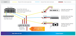
However, the network also has an increasing number of low bandwidth devices that still need power. While 4-pair cable can support these devices, a new copper solution is emerging. Single-Pair Ethernet (SPE) will deliver low bandwidth data over very long distances, potentially up to 1000m. These SPE systems will also deliver power via Power over Data Lines (PoDL). This will enable designers to minimize the number of Telecom spaces dedicated to these OT devices, mirroring some of the extended distance capabilities of fiber.
With the network of the future, hybrid fiber cables could be used to connect high bandwidth devices, traditional 4-pair and SPE copper cables could be used to connect low bandwidth devices.
What is clear is that the new hybrid cables are enabling fiber to reach deeper into the network, providing additional infrastructure choice for connecting devices that require high bandwidth, power and distance.
Kevin Paschal is a Systems Engineering Manager for CommScope, Inc. He is responsible for providing technical direction, training, and support to the Campus and Venue sales teams, Business Partners, and end users for the SYSTIMAX and Uniprise families of copper and fiber infrastructure solutions. He wrote this article on behalf of the TIA’s Fiber Optics Tech Consortium.

