Going the distance: What you need to know about breaking the 100-meter distance limitation
By members of the CCCA’s New Technology and Trends Committee
Local area networks (LANs) have historically been designed in a way that ensures all end devices are within 100 meters (m) of a telecommunications room (TR) to comply with industry cabling standards. Now with the adoption of smart building technologies, more devices than ever are being connected to and powered by the network. Today’s LAN environments commonly encounter situations in which a connected end device is located too far from the nearest TR to maintain the 100m distance limitation.
It has long been known that twisted-pair copper cabling is one standards-based option for connecting devices beyond 100m, but there is confusion in the industry about the distances that twisted-pair copper cables can reliably support at various transmission speeds and remote powering levels. To strategically address scenarios where a device is located beyond 100m with reduced risk, information and communications technology (ICT) professionals need to understand the pros and cons of the various options, technical factors involved, and key considerations surrounding testing to help them identify reality and navigate claims.
Cabling standards-compliant options
ANSI/TIA-568 cabling standards for commercial buildings define the minimum performance requirements for structured cabling to support a variety of applications (e.g., Ethernet, PoE, HDBase-T, DSL, etc.). These industry cabling standards are based on worst-case minimum performance of cabling system components, links, and channels to ensure an objective, realistic, and measurable basis for interoperability and competition in the marketplace. ANSI/TIA-568 cabling standards have long specified a 100m distance limitation for horizontal twisted-pair copper cabling channels, which includes a 90m permanent link with a total of 10m of patch cable. Maintaining a fixed, universal horizontal channel length facilitates extrapolating performance parameters to support increasing transmission speeds. As a result, the 100m distance limitation specified in industry cabling standards has been carried over through generations of twisted-pair copper cables, from Category 3 capable of supporting 10 Megabits per second (Mbits/sec) to Category 6A capable of supporting 10 Gigabits per second (Gbits/sec).
With emerging IoT and smart building initiatives, more devices in more spaces than ever need to connect to the network. To cover outdoor spaces, warehouses, parking garages, and other remote areas, it is common for an enterprise facility or campus to require a surveillance camera, access control device, wireless access point, or other device in a location beyond 100m from the nearest TR. To reduce cost and improve efficiency, many of these devices are also now digitally powered via remote powering technology like power over Ethernet (PoE), rather than connected to a traditional AC power circuit. Cabling standards-compliant options for connecting and powering devices beyond 100m include adding a new TR, using a decentralized extender device, connecting the device with fiber-optic cable and separately delivering power, or using a hybrid copper-fiber optic cable to deliver data and power. Each of these standards-based options has its pros and cons, described here
Adding a new TR: One option for connecting devices beyond 100m is to add another TR. This could be an actual room, or a mini TR housed within in a freestanding or wall-mounted cabinet. The benefits of adding another TR include compliance with industry cabling standards, centralized management, and the ability to support speeds up to 10 Gbits/sec and deliver up to 90 W of PoE. However, the cost of adding a new TR is difficult to justify if only needed to support a few remote devices located beyond 100m. Not only do TRs take up valuable real estate, but they require additional active equipment and associated power consumption, cooling, and maintenance.
Using an extender device: Deploying an Ethernet extender device within the horizontal cable plant is another option for supporting remote devices. Far less expensive than adding a TR, extender devices leverage existing twisted-pair copper cabling, and depending on the device, can support up to 10 Gbits/sec and up to 90 W of PoE. However, extender devices typically require local power, which adds expense. Locating an extender device out in the horizontal space also adds a remote point of failure and eliminates centralized management, which can make troubleshooting and maintenance more difficult, disruptive, and costly.
Connecting devices via fiber: Another option for extending distance to devices in the LAN is to connect the device via fiber-optic cabling. Per TIA standards, an OM3 or OM4 multimode fiber link can support speeds of 10 Gbits/sec to a distance of about 300m, or 1000 Mbits/sec to a distance of about 550m. While fiber is an ideal solution for these longer distances, the cost of fiber transmission equipment is difficult to justify for a few LAN devices located just 10 or 20 meters too far from a TR. Furthermore, end devices with a fiber input/output (I/O) port are limited in the marketplace. A media converter and copper patch cord are therefore often required to make the device connection. PoE media converters offer the benefit of delivering PoE power to the device but using fiber-optic cabling with media conversion still requires the higher cost of fiber transmission equipment. Like an extender device, PoE media converters are also a remote point of failure that require power.
Using hybrid copper-fiber cable: Even if a device does include a fiber port for connecting it directly to the fiber network and does not require a media converter, the device will need to get power through some other means than PoE if local power is not available. One option is to use a hybrid copper-fiber cable that includes fiber for the data transmission and copper conductors for power delivery. The use of hybrid copper-fiber cable still requires more expensive fiber transmission equipment, as well as a Class 2 limited power source (LPS) to deliver the power. Note that Class 2 power delivered over hybrid copper-fiber cable is not PoE. While PoE is a type of Class 2 power, it is only supported by twisted-pair copper cabling.
When using hybrid copper-fiber cable, it is important to carefully select the size of the copper conductors, which typically ranges up to 12 AWG. The gauge of the copper directly impacts how much power can be delivered over certain lengths. In addition, using Class 2 non-PoE power over hybrid copper-fiber cable requires careful planning and voltage drop calculations to ensure enough power to support a device based on its current draw and distance from the power source. Once deployed, if the conductor size is too small or the distance is too far to support the power requirements of the end device, the only options are to replace the cable, add additional copper conductors, or reduce the link length. This can significantly hinder moves, adds, and changes, as well as the ability to leverage the hybrid copper-fiber cable for future devices.
A more cost-effective approach
While not compliant with ANSI/TIA-568 cabling standards, the most cost-effective option for connecting devices located beyond 100m is to simply extend the distance of a twisted-pair copper cabling link. This approach requires no extra space, equipment, or points of failure. Regardless of length, twisted-pair copper cables also support familiar modular RJ45 connectivity and installation practices—other than pulling the cable farther than 90 meters from the TR, the installation process for a longer link is no different from any other twisted-pair copper cabling link. Using twisted-pair copper cabling also supports centralized management, facilitates troubleshooting and maintenance, and supports efficient remote power delivery via PoE directly from a PoE-enabled switch.
When comparing the various options for connecting a device located beyond 100m from the TR, it’s clear to see that twisted-pair copper cable is the most appealing from a cost standpoint as shown in the table.
The technical factors involved
Although twisted-pair copper cabling is the most cost-effective choice for extending horizontal cabling distances beyond 100m, there are several factors that must be taken into consideration. Because extending the distance of a twisted-pair copper cabling channel beyond 10 m is not currently supported by ANSI/TIA-568 cabling standards, it is necessary to look at application standards instead.
Cabling standards define the minimum performance requirements for structured cabling links, channels, and components to support an application usually to 100 m with the goal of ensuring interoperability between components from different manufacturers. Certification testing to cabling standards is performed at the time of installation, as often required by scope of work and to acquire warranty. Testing to cabling standards is conducted on cables that are not yet actively supporting an application, connected to a device, or transmitting data. Theoretically, cables that comply with cabling standards should ensure support for any application designed to be used with that specific type of cable to 100m. In contrast, application standards look at the ability of specific applications to run on a link segment, regardless of the cabling components and the distance.
Key performance parameters
Length-dependent performance parameters like insertion loss, propagation delay, DC resistance, and signal-to-noise ratio (SNR) are closely tied to the ability of a link segment to support a specific application to a specific length.
Key influencing factors
Insertion loss, DC resistance, propagation delay skew, and SNR that affect the distance a twisted-pair copper cable can support for a given application are impacted by several influencing factors—from speed and PoE level, to cable construction and quality, as well as a variety of design and installation variables. All these factors are why there are currently no industry cabling standards for extending the distance of twisted-pair copper cables beyond 100m.
- Transmission speed and level of PoE power—Faster transmission speeds operate at higher frequencies, which increases insertion loss. The amount of PoE power available at the end device also decreases with distance due to voltage drop. Therefore, the faster the speed and the higher the power, the less the distance that can be supported over twisted-pair copper cabling.
- Cable and patch cord construction—Insertion loss and DC resistance are largely dependent on the gauge of the conductors that are within twisted-pair copper cables. The larger the gauge, the less the insertion loss and resistance. Additionally, stranded conductors, such as those used in patch cords, exhibit higher insertion loss than solid copper conductors. Shielding and even the dielectric material used in the cable’s insulation and jacket material can also impact insertion loss and DC resistance.
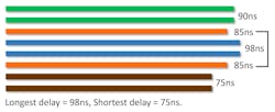
- Cable and patch cord quality—Inconsistent pair geometry and twist rates and variations in diameter, concentricity, contour, and smoothness of the copper conductors can cause DC resistance unbalance and propagation delay skew that impact distance capabilities. DC resistance is also a concern in low-quality and often counterfeit copper clad aluminum cables and patch cords. Aluminum exhibits more than 66% higher DC resistance than copper, which can easily exceed the 25 Ω limitation for PoE applications and also generate too much heat. Accordingly, copper clad aluminum cables are not compliant with industry cabling standards and do not meet UL safety listings per the National Electrical Code (NEC®).
- Network topology—How devices are connected to the network (i.e., directly with modular plug-terminated links or via outlets and patch cords), and the total number of connectors in the channel impact insertion loss and distance capability. The more connections in the channel, the greater the insertion loss.
- Heat rise and temperature—The amount of heat generated by the flow of DC current in PoE applications, the overall ambient temperature, and the ability of the cable to dissipate heat can all create heat rise in twisted-pair copper cabling. This increased heat increases insertion loss. Within bundles of cables carrying higher levels of PoE power, it is more difficult for heat to dissipate. Industry standards and the NEC® address heat rise in cable bundles carrying DC current by limiting bundle size. For 100m twisted-pair copper cabling channel lengths, industry cabling standards are specified at an ambient operating temperature of 20°C (68°F) and recommend reducing (de-rating) channel length for higher temperatures.
- Poor workmanship—Improper installation practices, such as exceeding cable bend radius, compressing or kinking cable, not consistently terminating all conductors, or not properly maintaining pair twist right up to the termination point can increase DC resistance unbalance and propagation delay skew that limit distance capabilities.
What’s the reality?
There are several IP-based network devices that operate at lower speeds, of 1000 Mbits/sec or less, and require lower levels of PoE power. Devices such as surveillance cameras, call boxes, access control panels, PoE lighting fixtures, time clock systems, intercom/paging systems, energy management systems, and environmental sensors and controls are examples of lower-speed, lower-power devices that often need to be located beyond 100m. For example, there may be the need to locate a surveillance camera out in the warehouse, an access control panel at the far end of factory, or an emergency call box in the parking garage. At lower speeds and lower levels of PoE power, performance factors such as insertion loss and voltage drop are less likely to impact distance capabilities.
In addition, most reputable manufacturers design quality twisted-pair copper cabling systems that exceed cabling standards and offer more headroom, including improved insertion loss, propagation delay, and DC resistance. While this helps ensure support for applications to 100m regardless of installation variables and environmental factors, it has also allowed several reputable manufacturers to qualify certain twisted-pair copper cables to support a variety of low-speed, low-power applications to distances beyond 100m. Many of these advanced cables are even promoted as offering extended distances for specific applications. In contrast, minimally compliant cables with no headroom are far less likely to support extended distances and are more prone to marginally pass or even fail at 100m distances due to installation variables and environmental factors.
Unfortunately, although many quality twisted-pair copper cabling systems can support lengths greater than 100m, there is still much confusion in the industry about the distances they can reliably support at various transmission speeds and remote powering levels. Much of this confusion stems from some manufacturers claiming the ability to support extended distances for high-speed, high-power applications based on inadequate approaches to testing and verifying performance at various lengths. The reality is that supporting transmission speeds of 10 Gbits/sec and higher-level Type 3 (60 W) and Type 4 (90 W) PoE to extended distances is extremely challenging—even for reputable, innovative manufacturers. Applications that require these higher speeds and PoE levels, such as the emerging high-throughput WiFi 6/6E deployments, are therefore not feasible over twisted-pair copper cable links that reach much beyond 100m.
When considering the use of twisted-pair copper cabling to extend distances beyond 100m, it’s important to carefully navigate the claims by verifying manufacturers’ technical specifications for their cables, understand testing requirements, recognize risks, and ask the right questions.
Understand testing requirements
When selecting twisted-pair copper cables for distances beyond 100m, it’s important to review manufacturer specifications and understand how the cables have been tested. Reputable manufacturers test their cabling systems to comply with the minimum performance requirements of cabling component standards. This ensures support for any application designed to run on that specific cable type (i.e., Category 5e, Category 6, Category 6A, etc.) to 100m. Installers then field test the cable plant to cabling standards to ensure that installed links also meet the performance and distance requirements to support applications designed to run on the specific cable. However, compliance with cabling standards does not indicate whether or not the cables will support applications beyond 100m. This is where application testing comes in. As previously discussed, application standards look at the ability of specific applications to run on a link segment, regardless of the cabling components and the distance, and considers parameters such as insertion loss, propagation delay, DC resistance, and SNR.
Reputable cabling manufacturers conduct rigorous lab testing and third-party verification of distances based on IEEE application standards (i.e., Ethernet, PoE, etc.) and various conditions, such as topology, ambient temperature, and end device requirements. They also conduct laboratory bit error rate (BER) testing using specific device network interface cards (NICs). BER testing sends actual Ethernet data packets at a specific speed in both directions to check for errors. It is through this comprehensive testing approach that many reputable manufacturers are able to warrant twisted-pair copper cables for specific applications and distances beyond 100m.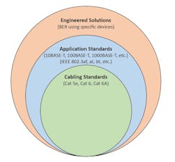
Application testing can also be conducted in the field and is recommended for twisted-pair copper cables in channel lengths greater than 100m. Application testing reduces risk by ensuring support for an application over a specific distance. BER testing can also be done in the field but unlike application testing, it evaluates a specific device over a specific distance and under specific conditions. In other words, BER testing is geared more for evaluating an engineered solution and can fail if any variables change, including the device, temperature, external noise, and other factors.
Recognize the risk of variability
For anyone considering twisted-pair copper cabling to connect a device beyond 100m, it’s important to understand that every device is unique. Equipment manufacturers design switch ports and devices to meet minimum requirements for successful transmission within application link segment limits, which is easily achieved with 100m of cabling. However, performance can vary in each device’s ability to accommodate transmission irregularities associated with extended distances. That means that an extended distance link that successfully connects two specific devices may not function if one of the devices is changed. This is true even if using the same vendors’ equipment, but a different type of device.
The variability that occurs in extended-distance links introduces uncertainty, which is why application testing is so critical—both in the lab via the cable manufacturer and in the field. If only BER testing was performed, swapping out devices and changing the conditions cannot guarantee performance, which eliminates the ability to futureproof.
Ask the right questions
Given the wide range of variables that impact distance capabilities and various marketing claims in the industry, it’s important to ask the right questions when selecting twisted-pair copper cables for extended-distance deployments. This is especially the case for vendors claiming that their cables can support higher transmission speeds and PoE levels to distances that appear too good to be true and/or are far beyond the specifications of trusted, reputable manufacturers. For instance, adhering to the following guidelines may significantly reduce risk.
- Ask your cabling manufacturer what type of testing was conducted to determine the advertised distance capabilities for a specific application speed and level of PoE. Buyer beware if rigorous laboratory-based application testing and BER testing were not conducted. If only BER testing was conducted, understand that changing the device or a single variable may prevent the link from functioning. Make sure to also ask for any testing documentation as proof.
- Find out if the cable is covered by warranty and for what distance, application, and PoE level, and what type of field testing is recommended and/or required to maintain that warranty. While most reputable manufacturers will a uphold warranty as long as the permanent link test passes for all application standards-based parameters except for length, it is recommended to always check on specific warranty requirements for extended-distance deployments.
- Request that the cabling manufacturers simulate your specific environment, equipment, and configuration to ensure it will function prior to installation. This is especially important for cabling manufacturers that cannot produce adequate application testing results and/or do not offer a warranty. If there is any uncertainty in the ability of a manufacturer’s cable to support an application and deliver the required level of PoE to a certain distance, it is better to look elsewhere or choose a standards-based solution for extending distance.
Closing thoughts
It wasn’t long ago that we saw cabling standards established, and now the industry simply wouldn’t operate without them. While industry standards do not currently address extended-distance deployments due to all the variables, there is light at the end of the tunnel—we are seeing movement in creating extended distance standards, which will help eliminate confusion in the marketplace and prevent manufacturers from making marketing claims without the testing to back them up. Collaborative efforts between several cable manufacturers, standards bodies, and distributors are already helping to establish verified methods of measurement that guarantee results and protect design intent for extended reach, standards-based installations. New single-pair Ethernet (SPE) standards that support low-speed 10 Mbit/sec devices to 1000 meters and PoE up to 13.6 W may also eventually address the need for greater distances in connecting sensors, actuators, relays, and controllers used in building automation systems and some security deployments. For this to come to fruition, equipment vendors will need to integrate SPE technology into their chipsets.
In the meantime, anyone looking to extend the distance of twisted-pair copper cabling beyond 100m should talk to their cabling manufacturer and ask the right questions to verify performance before investing. If marketing claims appear farfetched, look to reputable cable manufacturers that stand by empirical evidence and warrant their cables for applications and power levels to realistic distances. Consider that twisted-pair copper cables from even the most reputable and innovative manufacturers cannot typically support speeds of 1000 Mbits/sec or higher at the highest 90W Type 4 PoE much beyond 100 m due to physics. For lower-speed 100-Mbit/sec applications, which includes many types of devices, distances may reach significantly above 100m, especially at lower levels of PoE. For many low-speed devices, using twisted-pair copper cables from reputable manufacturers to extend distances beyond 100m is risk-free and highly cost effective. But at the end of the day, anyone looking to select twisted-pair copper cabling systems for distances beyond 100m should do their due diligence.
The New Technology and Trends Committee for the Communications Cable and Connectivity Association (CCCA) serves as a resource for well-researched, fact-based information and education on issues and technologies vital to the structured cabling industry. It encompasses several experts from CCCA member companies that include manufacturers of cable and connectivity, distributors, and material suppliers. For more information, visit www.cccassoc.org.

