Application Assurance with Copper Cabling
Key Highlights
- Twisted-pair copper cabling has evolved significantly since the 1990s, supporting increasing data rates and new applications like PoE and 10GBase-T.
- Design improvements, such as tighter twists and larger conductors, have been crucial in enabling higher frequency transmission and better performance.
- Installation practices, including minimizing pair untwist and proper termination, directly impact the system's ability to support advanced applications.
- Testing standards like TSB-67, TSB-95, and TSB-155 have been developed to verify installed cabling systems' performance for specific applications and speeds.
- Recent innovations include cables supporting distances beyond 100 meters, driven by larger conductors and proprietary manufacturing, with verification tools ensuring performance compliance.
Since the time twisted-pair copper cabling began supporting data transmission in the 1990s, the cable itself and the components within it have been designed and manufactured to ensure an installed circuit can indeed support the transmission of signals to achieve the prescribed data rate. While much has changed over the past three decades—including the refinement of installation practices, the ability to test performance characteristics of installed systems, and considerations for supporting power in addition to data transmission—optimizing the design and manufacturing processes that produce twisted-pair cable has remained a constant. Today all those factors play into an installer and cabling-system owner gaining assurance that their installed copper cabling system will support the applications for which it is intended: product design and manufacturing techniques, installation practices, and electrical-performance characteristic testing. This article will detail both historic and current trends in application assurance for copper cabling.
10-Mbit/sec 10Base-T Ethernet was one of the earliest networking applications to be “married” to twisted-pair cable. That association likely is how twisted-pair cable acquired the moniker “Ethernet cable,” a name that sticks more than 30 years later. Cable rated at Category 3 will support 10Base-T Ethernet. When Ethernet speeds increased tenfold to 100Base-T, accompanied by an increase in operating wavelength from a maximum of about 16 MHz to a maximum approaching 100 MHz, Category 3 cable was found to be insufficient to support that higher data rate.
Transmitting Ethernet signals over 100 MHz to distances up to 100 meters put a never-before-seen strain on the supporting twisted-pair cable. The answer was to more tightly twist the pairs within the cable so the conductors could successfully transmit the higher-frequency signals. The balance of a conductor pair’s twist enables that pair to transmit a 100-MHz signal with minimal degradation caused by attenuation or crosstalk. In a 4-pair cable, each pair has a slightly different twist rate to reduce crosstalk between pairs.
Additionally, the copper used as the conductor material for Category 5 cable generally is of higher quality than the copper used in Category 3 conductors.
In the mid-1990s, when 100Base-T was introduced and Category 5 cabling gained significant market share, the cabling industry began focusing on the importance of verifying that an installed cabling system can perform at a level that enables it to support its intended application(s). The years-long process of technical research and experimentation ultimately resulted in the publication of the Telecommunications Industry Association’s TIA Telecommunications Systems Bulletin TSB-67 Transmission Performance Specifications for Field Testing of Unshielded Twisted-Pair Cabling Systems. TSB-67 is the seminal document for the vital process of in-the-field certification/verification/qualification of installed cabling systems.
Another tenfold increase
When Ethernet achieved its next tenfold speed increase from 100 Mbits/sec to 1000 Mbits/sec or 1 Gbit/sec, the IEEE managed to do so without increasing the frequency range. 1000Base-T operates at a maximum of 100 MHz. The engineering behind this accomplishment is beyond the scope of this article, but in brief, 1000Base-T operates via 4-pair full-duplex transmission, meaning each wire pair both transmits and receives data simultaneously. Suffice it to say the complex modulation technologies built into 1000Base-T full-duplex transceivers place previously unprecedented strain on a Category 5 cabling system.
Despite the IEEE’s intention to develop 1000Base-T to operate over the installed base of Category 5, field testing revealed that not all Category 5 systems were up to the task. Once again a TIA document addressed the issue. TSB-95 Additional Transmission Performance Guidelines for 4-Pair 100 Ohm Category 5 Cabling identified electrical-performance characteristics, and the acceptable limits for those characteristics, that identify whether or not a Category 5 circuit can support 1000Base-T. For 100Base-T performance, a Category 5 link had to achieve certain performance for electrical characteristics that were not considered when the original Category 5 test parameters were developed. Whereas a Category 5 test suite includes wiremap, length, attenuation (loss), and near-end crosstalk, TSB-95 prescribes delay skew, return loss, equal-level far-end crosstalk (ELFEXT) and power-sum equal-level far-end crosstalk (PSELFEXT).
While the IEEE developed the 1000Base-T standard, that standards development organization maintained a close liaison relationship with the TIA not just to develop the content of TSB-95, but also for the TIA to establish an entirely new Category rating for twisted-pair cabling—Category 5e. The “e” stands for “enhanced,” as Category 5e cabling delivers better electrical-performance characteristics than Category 5 and includes parameters not included in the Category 5 spec.
Spotlight on workmanship
One reality that came to light when installed Category 5 was tested for its fitness to support 1000Base-T, was that installation workmanship plays a role in the link’s performance—and workmanship was not always top notch. One such issue is pair untwist at the point of termination. Because the tight, balanced twisting of conductors enables higher performance, the extent to which an installer untwists each pair at the point of termination plays a significant role in either maintaining or degrading that performance. The less untwist, the better the performance. The Category 5e standard includes a requirement that an installer may untwist no more than 0.5 inches of a conductor pair between the cable jacket and the point of termination.
In the Category 5e standard, the industry gained not only a set of performance specifications for a cabling system, but also some installation requirements (e.g. 0.5-inch pair untwist), and a closely associated set of test parameters established to ensure an installed system meets the prescribed specs.
Category 5e was the third twisted-pair cable performance type to be hand-in-glove associated with an Ethernet application (after Category 3 for 10Base-T and Category 5 for 100Base-T). Since the time that Category 5e and 1000Base-T were finalized, the dual paths of cabling performance Category and network application have departed from their closely-in-parallel association. Their individual paths have diverged at times, and crossed at other times.
Nonetheless, a trifecta of sorts was established in the evolution that culminated in 1000Base-T. That trifecta is: 1) A cable that is designed and manufactured optimally to achieve certain performance characteristics; 2) workmanship issues associated with the installation of this cable; and 3) test parameters that evaluate the installed cabling system’s ability to support an intended application.
Let’s take a look at a few examples of how that trifecta has held up over a couple decades.
In 2002 the TIA published the Category 6 cabling standard. Specified to a maximum frequency of 250 MHz, Category 6 was not developed in lockstep with a specific speed of Ethernet or any other data-transmission application. It came to market as an upgrade over Category 5e, providing headroom (better performance capability) over 5e in electrical-performance parameters, and delivering positive attenuation to crosstalk ratio (ACR) to nearly 250 MHz—positioning Category 6 to support applications yet to be developed in that frequency range. The same year the TIA published its Category 6 cabling standard, the IEEE finalized its standard for optical 10-Gbit Ethernet (IEEE 802.3ae). While 10-Gig over copper was still just a glimmer in the eyes of IEEE engineers in 2002, Category 6 cabling was poised to support that application, eventually, should it be defined to operate at frequencies up to 250 MHz.
One notable difference between Category 6 and Category 5e is Category 6’s copper conductors typically are 23 AWG in size—larger than the 24-AWG size of Category 5e conductors. Electrically speaking, a larger conductor has less resistance than a smaller conductor. In the case of a Category cable, larger conductors enable improved resistance to noise, reduced signal loss, higher data rates, and greater bandwidth (operating frequency). Cat 6’s 23-AWG conductors are a significant reason the cable achieves a 250-MHz bandwidth.

Seizing power
In 2003, the IEEE finalized the Power over Ethernet (PoE) standard, IEEE 802.3af. Though the technology is universally referred to as “Power over Ethernet,” in reality, direct current (DC) power is delivered not over Ethernet packets or frames, but rather over the twisted-pair cabling that simultaneously supports the delivery of DC power and data. With a significant installed base of Category 5e and some Category 6 deployed in the field, early adopters of PoE had access to capable cabling infrastructure that supported the application.
Later versions of PoE increased the amount of power transmitted by the power sourcing equipment (PSE), and the amount received by the powered device (PD). The original 802.3af generated up to 15.4 Watts at the PSE and delivered up to 13 W at the PD. In the 802.3at specifications published in 2009, PoE technology generates up to 30 W at the PSE and delivers up to 25.5 W at the PD. And the 802.3bt specifications, published in 2018, define up to 90 W at the PSE and 73.3 W at the PD.
The second and third generations of PoE demanded certain electrical performance out of twisted-pair cable that data transmission, and even the first generation of PoE, did not demand. As PoE evolved, some versions of the technology placed current on all four pairs of a cable, rather than just two pairs. Also, PoE is common mode voltage, as opposed to data signals that operate in differential mode. That means when PoE is deployed, both conductors in a pair receive either positive voltage or negative voltage. By contrast, when data is deployed, one conductor in a pair receives positive voltage and the other conductor in the pair receives negative voltage.
Imperfections in the cable (i.e. design or manufacturing imperfections), or imperfections in termination practices can cause a cable to exhibit DC resistance unbalance. Cables with larger-sized copper conductors exhibit better DC resistance unbalance performance than those with smaller-sized conductors, so it is generally true that the larger the conductor size, the more capability the cable has to support PoE. When PoE is applied to a cable with poor DC resistance unbalance, the current divides unevenly between the conductors, resulting in excess heating in the cable, PSE, and PD.
Several actions can be taken to avoid DC resistance unbalance, or to mitigate its effects. Installers can use better-performing cables and properly terminate those cables as a preventive measure. They also can limit the number of cables in a bundle to avoid the potential for excessive heat generation.
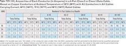
Even before the publication of the IEEE 802.3bt standard, commonly referred to as “PoE Plus Plus,” laboratory examinations of heating within cable bundles eventually led to requirements within the 2017 National Electrical Code limiting the number of cables allowed in a bundle based on the cables’ copper-conductor size. These requirements apply for any twisted-pair cable that does not carry the “LP” rating, which stands for Limited Power and indicates a cable’s ability to support PoE without experiencing excessive temperature rise (meaning experiencing minimal, inconsequential temperature rise). Several manufacturers of twisted-pair copper cables offer LP-rated cables.
Purpose-built cables
While LP-rated cables are an option for installers and end-users, many twisted-pair cable manufacturers offer products that are not LP-rated but have been designed and manufactured to support PoE applications. Generally these cables have larger conductors (as large as 22 AWG), the conductors can be solid copper rather than stranded copper for better resistance, and the cables have higher heat ratings—meaning they can operate satisfactorily in higher-temperature environments. Some of these cables are shielded rather than unshielded, to minimize interference.
The discovery that DC resistance unbalance performance affects a cable’s ability to sufficiently support PoE generated demand for a means of verifying that performance within an installed link. This demand set several test-equipment manufacturers to work developing new capabilities or tools, or educating users about the capabilities of their existing products to test a link for parameters specifically associated with PoE support.
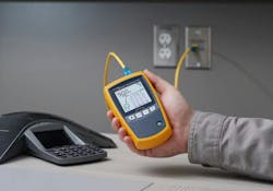
Today several test-equipment manufacturers offer verification tools that test cabling links for performance parameters that are specifically related to PoE. Several of these testers have the term “PoE” in their names. Some of them also act as PoE PSE simulators, enlightening their users not only on the cabling’s response to PoE transmission, but also the readiness of the PD to receive PoE direct current.
Over the decade and a half that PoE went from introduction to third-generation standard, the dual paths of twisted-pair cable Categories and Ethernet speed progression also evolved. Category 6A (TIA standard published in 2009) and 10GBase-T (IEEE standard published in 2006) match up in much the same way Category 5e and 1000Base-T did.
As is the IEEE’s practice, the Ethernet standards-development group made every effort to define 10GBase-T so it would operate over the installed base of twisted-pair copper cabling. At the time of 10GBase-T’s development, Category 6 was the highest-performing twisted-pair cabling on the market. Cat 6’s ability to support 10GBase-T was reminiscent of Cat 5’s ability to support 1000Base-T. This time, workmanship issues were not so much the issue as the physical limitations of the cable as it had been designed and manufactured.
Alien takeover
10GBase-T employs full-duplex four-pair transmission to a maximum frequency of 500 MHz. In addition to a list of internal electrical-performance characteristics that are stressed by this transmission scheme, it also causes the phenomenon called alien crosstalk, in which noise generated by one cable adversely affects neighboring cables.
Testing showed that pristinely designed, manufactured, and installed Category 6 cabling can support 10GBase-T to a distance of between 37 and 55 meters. The TIA developed and published TSB-155, which described procedures for testing Category 6 cabling for its ability to support 10GBase-T. Power-sum alien crosstalk (PS-AXT) tests involve the test technician identifying a disturbed or “victim” cable, and testing it while using devices at the far end of the link that simulate disturbers. These disturber simulators are plugged into multiple ports on the far end, to simulate the combined effects of alien crosstalk from multiple cables on the cable under test.
This test process is a significant departure from the “just-press-autotest” procedure technicians had gotten accustomed to while twisted-pair cables to previous generations of specifications. Along with these additional procedures in the test process, cable-installation practices changed with the advent of 10GBase-T and alien crosstalk. Cable bundling came under specific scrutiny, and installers were instructed to lay cables loosely in support equipment like trays. The tight bundling procedures that for years provided a visual representation of a professionally installed cabling system, now significantly increased the risk of cable-to-cable alien crosstalk.
Category 6A cable is specified to 500 MHz, typically includes 23-AWG conductors, delivers performance enhancements over Category 6, and is constructed to minimize the possibility of alien crosstalk. In addition to being an optimized enabling technology for 10GBase-T, Category 6A also is popular for PoE support. The larger-gauge conductors are the primary asset Cat 6A offers for high-power PoE, but its ability to support 10GBase-T to a full 100-meter channel position it as a future-ready medium in networks that could upgrade to higher speeds, greater PoE power delivery, or both.
Step back in speed, step up in capability
In 2016 the IEEE published the 802.3bz specification, which defines 2.5-Gbit/sec and 5-Gbit/sec data transmission. Departing from the traditional tenfold speed increase (10 Mbit/sec to 100-Mbit, to 1-Gbit, to 10-Gbit), 2.5GBase-T and 5GBase-T were developed, at least in part, to provide a sort of “backhaul” support for high-speed wireless LAN transmission. By the 2016 publication of these standards, the installed base of Category 5e and Category 6 cabling was massive, and conventional wisdom held that 2.5G could operate over Category 5e or Category 6, while 5G could operate over Category 6. While that can be true, history repeated itself yet again and scrutiny of the installed base revealed some cabling was up to the task while some was not.
By the time this technology was introduced, test-equipment manufacturers offered a variety of instruments that conduct “speed tests” to determine a cabling system’s ability to support specified transmission speeds. These types of tests, coupled with parametric measures of key electrical-performance characteristics, can deliver a level of assurance to cabling-system owners. For 2.5G and 5GBase-T in particular, the performance metric alien limited signal-to-noise ratio (ALSNR) came to the forefront. Extensive field and lab testing revealed that Category 5e and Category 6 cabling can support 2.5G and 5GBase-T respectively, under some conditions, but Category 6A provides the greatest application assurance with the lowest risk of failure.

Going the distance
Today, the capabilities of twisted-pair copper cable are being stretched not so much with new, higher transmission speeds or even higher levels of DC power, but with longer distances. For decades, best practices for network designers dictated any link length exceeding 100 meters included fiber-optic cable rather than twisted-pair copper. 100 meters was, as a practical matter, the maximum distance for twisted-pair.
That 100-meter limit has been imposed by the definitions and specifications in TIA cabling standards, not necessarily by the physical or electrical limitations of cables or connectivity. Over the past few years, several manufacturers of twisted-pair cables have introduced products that support data transmission and/or PoE transmission beyond 100 meters. These cables are non-standard by definition, because of the 100-meter distance limit imposed by TIA standards. But as a practical solution to real-world, in-the-field connectivity challenges faced by users around the world, the cables are viable products that can represent significant economic savings versus deploying other media types or products such as PoE extenders.
Once again, componentry within the cable—particularly including conductors—is a difference maker. Some of the most recently introduced cables that deliver greater-than-100-meter distances incorporate 21-AWG conductors, which further improves the cable’s DC resistance performance and thus its extended-distance capability.
Test-equipment providers have worked with several providers of these cables, to import the manufacturers’ proprietary specifications for their respective products. With these specs imported, test-equipment users can select the cable brand name and run a test that will verify the installed cable’s performance metrics at specified distances.
In many cases, aside from working with larger-than-typical conductors during the termination process, the installation of these cables is typical of other twisted-pair cable types.
In the decades since twisted-pair cable emerged as an enabling technology for 10-Mbit/sec Ethernet transmission, providers of this cable type have driven their evolution to a point at which today, these cables can simultaneously deliver data and direct-current power over distances once believed to be unreachable. Throughout it all, the trifecta of cable design and manufacture; installation techniques; and the ability to verify performance have been central to providing assurance and peace of mind to network owners.
About the Author

Patrick McLaughlin
Chief Editor
Patrick McLaughlin, content director for Cabling Installation & Maintenance and Endeavor B2B's Digital Infrastructure Group, has covered the cabling industry since the 1990s. He has authored hundreds of articles on technical and business topics related to the specification, design, installation, and management of information communications technology systems. McLaughlin has presented at live in-person and online events, has directed cablinginstall.com's webinar programs for 20 years, and administers the annual Cabling Innovators Awards.
Voices of the Industry

