Unique building requires creative multimedia design
Multimedia infrastructure cabling allows the network to grow and evolve with newer and faster technologies.
Dave Reusch
Mod-Tap
In the summer of 1992, design engineers at Mod-Tap Network Services were presented with the opportunity of developing a new multimedia local area network (LAN) for the medical department of the Massachusetts Institute of Technology (Cambridge, MA). As one of the original development sites for a proprietary 10-megabit-per-second token ring system in the early 1980s, the network needed a major upgrade. Over a three-year period, a well-planned, carefully orchestrated program of evaluation, design and implementation has provided this MIT group with a standards-based, modern client/server network architecture that meets all its LAN requirements.
The Network Services team first reviewed the system layout to find out what specific problems existed. Next, they determined whether the network cabling in place could be reused or should be replaced. After it was agreed that a new network using some of the existing cabling should be installed, the team designed a multimedia cabling infrastructure for this unique building.
The medical department building, which has six floors--five above ground and a basement--was built on reclaimed land. Its design includes an earthquake joint that allows the building to settle over time, without any structural weakening. This seam separates the building into two halves (north and south), and cable cannot be bridged across the above-ground floors. Two wiring closets were installed on each of the first four floors and, because the fifth floor exists only on the north side of the building, only one wiring closet was needed. The basement floor, which also has no seam, is likewise serviced by one wiring closet located on the south side of the building.
Evaluate current system
In the token ring network, the primary medium was Type 1 cable, serving approximately 300 users. The users on each floor were served by a ring, and these rings were connected to a larger ring that linked the individual wiring closets. The central hub for the network was the server room--housing the main file servers for the network--and the associated wiring closet.
In addition to problems with the Type 1 cable plant, the network was plagued by constant ring crashes and system-wide problems caused by "dirty" power supplied to PCs and network hardware. Given the level and complexity of these problems and the system management required to maintain a high level of service to the user base, the information systems (IS) group decided to investigate the replacement and upgrade of the network.
The Mod-Tap team reviewed the layout of the network cabling and hardware, and interviewed the IS group to pinpoint the causes of the network problems. They found that the electrical service had sags and surges greater than those that most network equipment could withstand in terms of voltage levels and duration. Furthermore, the Type 1 cable was fraught with ground loops and improperly terminated connectors. The electrical deficiencies were exaggerated by the general condition of the existing network cabling, and the complete replacement of the power lines in the affected areas was deemed too expensive. It was decided, therefore, to provide new power only to critical areas.
Salvage or replace?
Once the primary cause of network difficulties was established, the next question was whether the network cabling could be renovated and reused. The Type 1 cabling could be salvaged, but it would require a major network reconfiguration and replacement of damaged cables, as well as retermination or replacement of connectors and patch cables.
The Network Services team recommended replacing the entire cabling system, but one other option had to be considered. An existing network of unshielded twisted-pair (UTP) cabling had been installed for the telephone system in the late 1980s. It had sufficient capacity in most areas to support data communications consisting of 4-pair UTP cable from wiring closets on each floor to user locations.
An evaluation of this cabling indicated that it would most likely support the proposed network communications; however, the team doubted whether it would support the migration to future technologies that might not be so forgiving of the media quality and characteristics as 10Base-T Ethernet. Another concern was the security of the network, because this cabling was not--and would not be--under the control or management of the medical department IS group.
It should be noted that, given the sizable investment for the new network, MIT expected the cabling infrastructure to have a usable lifetime of at least 10 to 15 years, no matter which network was chosen. Given all these factors, the team abandoned the idea of using the existing UTP cabling in favor of all new media.
The larger question, however, was whether to stay with the proprietary network technology and accompanying operating system or migrate to a new, standards-based platform. Everyone agreed that a new network was required. One deciding factor was that the existing network had no management or analysis tools and, therefore, no way to evaluate the problems that were disrupting the system. Another consideration was that the existing system--and Type 1 cable in general--does not have a broad base of industry support.
The next steps in the design process were to determine the current network load and the appropriate technology and architecture of the cabling plant required to support it. Concurrent with the network-technology selection process, the design team performed an evaluation of the network load, or use. They attached a monitoring device to the network to record network traffic volume, including the size of packets, peak interaction periods, error rates, retransmissions and other analytical data. To ensure an accurate picture of the network communications traffic, this monitoring was conducted over several days. For the first time since the network was installed, the MIT medical department IS personnel had an accurate picture of the network`s operational characteristics and inherent deficiencies.
In addition to providing direct input to the research, the team asked other consultants with specific expertise in various technologies to present the pros and cons of different net- work topologies and platforms. Consideration was given to 16-megabit-per-second token ring, Ethernet, Fiber Distributed Data Interface (FDDI) and combinations of the three topologies. Beyond the merits of each technology, another influence was the desire to adopt a technology that would fit the MIT campuswide network model. Primarily because of the proprietary nature of the current network, the medical department did not have much interaction with the campus network at that time. An important requirement for the system selected was its ability to integrate into the campus network community.
The group agreed that the best choice for the new system was 10Base-T Ethernet-to-the-desktop. Given the size and complexity of the client/server interaction and the throughput requirements, the design included placing the file servers onto a Class A FDDI ring. (This scenario is sometimes referred to as a server "farm.")
Network architecture
The information from the network traffic model had a direct influence on the decision to place the server farm on an FDDI ring instead of placing the servers on an Ethernet segment or distributing them to other locations in the network. Using this architecture, the team decided to include six subnetworks in the design, five of which would be Ethernet and one FDDI. To control the interaction of the subnetworks and to create the desired segmentation, they placed a router at the center of the network.
This design calls for a main distribution frame (MDF) and four intermediate distribution frames (IDFs). Because the building is split down the middle by the barrier seam, this creates two riser pathways. The MDF was placed in the basement and IDFs were located on floors two and four; two on each floor, one in each riser (north and south).
More IDFs could have been included--for example, one on each floor for each riser--but the horizontal distance to the farthest desktop was well within the 90-meter maximum dictated by the TIA/EIA-568A standard. It was therefore more economical, in terms of network hardware, to consolidate the design to four IDFs, which calls for fewer wiring concentrators and more easily fits the model of subnetworks. One network wiring concentrator, with the physical capability to support the number of users, was located in each IDF. A fifth hub and the router were placed in the MDF for users on the basement level.
For cabling to the desk, the team defined 4-pair Category 5 UTP, terminated at either flush- or surface-mount single-gang wall plates at the user location. At the distribution frames, all horizontal cabling was terminated on rack-mount Category 5, RJ-45 patch panels. Because the IDFs were in public-access areas, the team recommended enclosed cabinets.
With the horizontal cabling plant defined, the design team turned its attention to the backbone cabling plant. Optical fiber was the obvious choice for the backbone cable for several reasons: riser space was at a premium; MIT wanted the system to support future bandwidth-intensive technologies; and lightweight, small-diameter fiber-optic cable would be easier to install in the riser. Multimode fiber-optic cable was chosen because the distance between the MDF and the farthest IDF (fourth north) was approximately 250 feet.
This backbone cabling would make available a worst-case theoretical bandwidth of approximately 1.6 gigahertz at an operating wavelength of 850 nanometers, and almost 5.5 GHz at 1300 nm for each strand in the cable--more than enough to meet MIT`s backbone-communications requirements for the usable life of the cable plant. The design team specified eighteen strands in each backbone MDF-to-IDF run to provide a sufficient number of physical connections and ensure that spare strands of fiber were available to replace any fibers damaged over the life of the system.
For additional fault tolerance, the team designed a horizontal "tie" cable between each pair of IDFs on floors two and four--the only cable to span the dividing seam. In the event of a failure in the primary link between any IDF hub and the router in the MDF, the equipment would automatically switch over to the other riser path using the tie cable. In addition, IS personnel could make any repairs without the pressure of system downtime, especially important because the MIT medical department is a functioning hospital with many mission-critical areas.
Given its broad-based industry support and to ensure connectivity to virtually any vendor or technology, the ST connector was chosen as the primary interface for the optical-fiber cable. The FDDI equipment would be connected into the optical fiber infrastructure with hybrid ST-to- FDDI patch cables.
Final design details
Once the team had completed the design of the infrastructure cabling, the server farm, consisting of four multigigabit devices, required some special consideration. A user who was accessing files on the network did not necessarily go to only one server to retrieve the information. Sometimes the network might have to access pieces of information from all servers, compile it, and then deliver the package of information to the user. This process and the number of users who may demand service at any one time required a higher-speed technology--one of the primary reasons for choosing FDDI.
Three of the servers were collocated in a basement room next to the MDF, and the fourth was in a laboratory on the first floor. The collocated servers were interconnected by using patch panels; however, the integration of the fourth server into the ring required a run of horizontal fiber to the first-floor laboratory from the MDF. A six-strand multimode fiber-optic cable was designed for this connection, with four strands used for the server connection (two in and two out) and two spare strands in case of damage to one of the primary strands.
The cabling plant design required one last consideration: The IS group, located on the basement level near the MDF, required direct access to the FDDI network. The design, therefore, included additional horizontal runs of optical fiber between the MDF and the IS offices. This would allow the IS staff to move servers into the area, if desired, and to access the ring directly for maintenance and monitoring purposes.
One task remained before going out for bid: a migration plan to move from the old network to the new. The aim was to install, configure and activate the new system alongside the old, bringing users over to the new system in phases. For this to work, however, the two networks would have to be tied together at the server level so users of both systems could access the same data. Mod-Tap brought in a consultant with specific expertise for this concurrent network operation.
Implementation
Everything was now in place to move from the design phase to implementation. The company created a specification document that defined the various aspects of the system, including the infrastructure cabling, network hardware, installation requirements, migration specifications and ancillary information required for contractors to bid on the project. Managing the bid process on behalf of the medical department IS group, Mod-Tap solicited bids from 10 companies.
Upon completion of the bidding process, Network Services helped the IS group reduce the pool of candidates to three. The final selection was made based upon price, contractor credentials, innovative design input, and ability to meet and support the installation timelines and subsequent migration from the old to the new system.
The network was installed during the next several months, with the cabling placed first. A few design modifications were required; for example, the original plan called for the riser pathway on each side of the building to be a service shaft that runs through all the floors. The coring equipment would not fit in the space, however, and the shaft housed a delicate trolley system used for the physical transference of medical records, which made the shaft unusable for the riser cabling. A separate bid, therefore, had to be put out for coring the floors and installing conduit to create a riser pathway on each side of the building.
Once the cabling was completed, the hardware was installed in the distribution frames. After a burn-in period to ensure that all components functioned correctly, the migration process started. As each group went online with the new system, the bugs were worked out and the old system was deactivated.
The MIT medical department is now online with the new network, and the problems and management issues inherent to the old network have been eliminated. In addition, the system has joined the campuswide network, so that users can now communicate with other areas of MIT.

Dave Reusch reviews design blueprints with Jan Smith of the information systems group for the MIT Medical Department`s new multimedia cabling installation in Cambridge, MA.
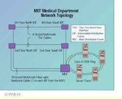
The network includes the main distribution frame in the basement, with two 18-strand multimode riser pathways to intermediate distribution frames on floors two and four. In the event of a failure, the equipment automatically switches over to the other riser path using the four-strand multimode "tie" cable that spans the building`s dividing seam.
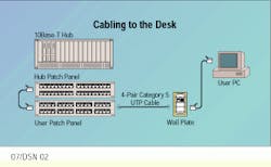
Cabling to the desk is 4-pair Category 5 unshielded twisted-pair cable terminated at flush- or surface-mount single-gang wall plates.
Dave Reusch, registered communications distribution designer (RCDD), is general manager at Mod-Tap Network Services, Harvard, MA.

