Using laser-optimized multimode fiber for 1G and 10G campus backbones
From the November, 2013 Issue of Cabling Installation & Maintenance Magazine
In many cases Om3 or Om4 fiber will provide a robust, cost-efficient solution.
By David Kozischek, Corning Cable Systems
System designers are routinely asked two questions: 1) How do I determine the type of fiber needed for my campus backbone? And 2) How do I determine the number of fibers needed for my campus backbone?
Both of these questions require analysis to help the network designer make the best decision. This article provides design guidance to help put some analysis behind the decision making process. It includes the following areas of consideration.
- Fiber types used in the campus backbone
- Designing the cabling infrastructure
- Determining the fiber type and fiber mix for 1- and 10-Gigabit Ethernet (GbE)
- Determining the total fiber counts
- Final fiber count and fiber mix
- Rules of thumb
This article uses a network model to evaluate different installation scenarios based on 1- and 10-GbE as the local area network (LAN) protocol, and analyzes the benefits of using laser-optimized 50-µm multimode fiber in these networks.
Fiber types used in the campus backbone. Before Gigabit Ethernet, fiber type was an easy decision in campus design. Standard 62.5/125-µm multimode fiber (Om1) was used for any application up to 2,000 meters and network speeds up to OC-12 (622 Mbits/sec); and singlemode fiber was used for anything else. Gigabit and 10-Gigabit Ethernet changed these rules. Laser-optimized 50-µm multimode fiber (Om3, Om4) was introduced with increased bandwidth performance for 10-GbE, and the performance was included in the ANSI/TIA-568 standard. A summary of the fiber types and their typical performance is shown in the table on page 14.
The table includes both overfilled launch (OFL) and effective modal bandwidth (EMB) fiber parameters. OFL bandwidth (OFL BW) is used for light-emitting diode (LED) electronics operating over multimode fiber. The EMB bandwidth simulates operation on multimode fiber based on the use of GbE or 10-GbE vertical-cavity surface-emitting lasers (VCSELs) at 850 nm.
Designing the cabling infrastructure. Before attempting to determine the fiber types, determine the cabling topology for the campus. To do this, we will create a campus backbone model.
The backbone model assumes each building contains multiple floors with a minimum of one telecommunications room (TR) per floor. All distances are in meters and include the length from the building entrance to the main communications room. All network analysis is based on a GbE building-to-building fiber backbone with provisions for 10-GbE.
The design of the cabling topology can be separated into three smaller steps to help the network designer make the best choice. These steps include: Consult the TIA-568 standard; determine the location of the main, intermediate and horizontal crossconnects; determine the fiber lengths. Let's look at each of these steps.
Consult the TIA-568 standard. The standard gives design rules for cabling the campus backbone. They include: the backbone cabling shall use hierarchical star topology; there shall be no more than two levels of crossconnects; connections between any two horizontal crossconnects (HCs) shall pass through three or fewer crossconnects.
Maintain length requirements between the main crossconnect (MC), intermediate crossconnect (IC) and HC and in accordance with ANSI/TIA-568-C, where cable lengths are dependent upon the application and upon the chosen media type.
Determine the location of the MC, ICs and HCs. Before determining the location of the MC, ICs and HCs, define the function of these crossconnects. The MC is a crossconnect for the first-level backbone cables, entrance cables and equipment cables. The IC is a crossconnect between first-level and second-level backbone cabling. The HC is a crossconnect of horizontal cabling and other cabling, such as backbone or equipment cabling.
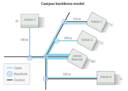
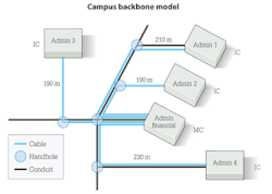
In the campus model, assume each TR will act as the HC and connects to the building IC. Next, the ICs connect back to the MC in a physical star topology. The key decision is how to determine the location of the MC. The location of the MC can be dictated by where most of the servers, switches and routers are housed. If a certain building is already chosen based on these criteria, then all length calculations would be from that point. If any of the buildings can act as the MC, determine which building is centrally located in order to minimize cable lengths. In the illustration, selecting the administration financial building as the MC and the other buildings as the ICs yields a practical solution, because it is centrally located on the campus. The illustration also shows the cable route and distance.
Determine the fiber lengths. Though the cable is deployed as a physical star, other logical topologies can be considered, such as a ring and mesh network. To get a better understanding of the fiber distances, it is a good idea to construct a matrix that defines the fiber distance between any two buildings in the backbone.
Remember that the admin financial building is the MC for our campus, so all network connections flow through the MC. The table on this page with length-calculator information depicts this concept for our campus model.
Choosing the fiber type and fiber mix for 1- and 10-Gigabit Ethernet. Based on the cable routes chosen for our campus model, the next step is to determine the fiber types. Because we are concentrating on the campus backbone (building-to-building links) and 1- and 10-GbE technologies, we need to look at length restrictions based on fiber type. This comparison is shown in the table on cabled fiber types on page 12.
The GbE distances shown in the table are a function of the fiber core type and the associated EMB. Though Om1 fiber has a larger installed base, is it worth switching over to 50-µm (Om3 only)? Also, what should the fiber mix of multimode to singlemode be? To answer these questions, we will apply a logical networking scenario to the physical topology. In the campus model, a redundant point-to-point logical star topology is implemented. This architecture uses redundant electronics in all buildings to reduce single points of failure. In this example, the campus backbone is sized for 1-GbE with provisions for a 10-GbE network.
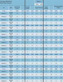
The first step in implementing this architecture is to determine the fiber counts for the GbE backbone. The table that discusses backbone fiber counts (p. 18) uses assumptions about the numbers and amount of networking equipment in order to determine fiber counts. Additionally, because the logical topology is a point-to-point, the distances from the previous table--the matrix-style table that calculated fiber lengths in meters--are also used in this effort to determine fiber counts.
In the analysis that follows, we are going to look at migrating the backbone from 1 to 4 Gigabits using standards-based (IEEE 802.3ad) Ethernet trunking. The campus will also use two switches per building. We will not consider 10-GbE trunking at this time.
To analyze this network, look at the number and types (multimode and singlemode) of fibers that are lit in migrating the network to the logical topology. Look at multiple building-to-building (MC-to-IC) links, and calculate the number of fibers used.
The large table illustrates that 16 fibers are needed for each building-to-building link for the 4-GbE backbone:
2 links per building x 2 fibers per GbE link x 4 GbE trunk per link = 16 fibers
This also shows that to implement a redundant star topology, four fibers are needed for each building-to-building link for 10-GbE migration.
Choosing the total fiber counts. The next step is to determine the number of multimode fibers and singlemode fibers that are needed to implement this redundant star topology. This is accomplished by referring back to the table on building-to-building link lengths, and comparing the fiber type to the length restrictions for 1- and 10-GbE in the table on cabled fiber types.
Analysis is then conducted, trying to size the backbone to maximize the use of 850-nm VCSELs for serial 1- and 10-GbE. Even though multimode fiber can operate at the 1300-nm window for 1- and 10-GbE, it is more cost-effective to operate at 850 nm over multimode, due to the lower cost of transceivers.
The last step in choosing total fiber counts is to determine the final fiber counts for each cable. The fiber-count-calculator table gave us the minimum fiber counts to migrate the backbone trunk from 1 to 4 GbE with migration to 10 GbE, but what about other applications that might run across the network? Applications such as security video, card readers, videoconferencing and control systems are applications that require additional fibers. Unless all applications are going to operate over an IP network, you will also need to add spare fibers in the cables. Spare fiber can run anywhere from 25 percent up to 100 percent in a campus design. In this campus model, a 50-percent spare rule is used. With this information, the fiber matrix illustrated in the table was generated.
The table shows the fiber-count and fiber-mix breakdown, based on the different fiber types. As shown, the fiber mix can change based on the type of multimode fiber and the length restrictions for 1- and 10-GbE. To determine which fiber mix is the most-effective price, analyze the price of the GbE transceivers, 10-GbE transceivers, and the fiber types for this campus backbone.
Cables that contain Om1 or Om2 are assumed equal in price. Om3 and Om4 have associated premiums.
LX cards for GbE over singlemode fiber typically cost two times more than SX cards for GbE over multimode fiber.
LR cards for 10-GbE over singlemode fiber typically cost two times more than SR cards for 10-GbE over multimode fiber.
The results are shown in the price-analysis figure on page 12. For this network topology, using a hybrid cable containing laser-optimized Om4 multimode fiber is the lowest-cost solution versus other cable mixes. The reason the laser-optimized fiber is the most advantageous is that more links are using 850 nm for 1- and 10-GbE. Ethernet can migrate from 1- to 4-Gbits/sec through trunking, then a 10-GbE network can be installed--all supported by laser-optimized fiber.
The other item to note from the figure is that the laser-optimized Om4 multimode fiber solution is 30-percent cheaper than operating this network over only singlemode fiber--even though the cable cost is higher than that of other solutions. Although a singlemode fiber can support 1-GbE up to 5 km and 10-GbE up to 10 km at 1310 nm, the higher premium paid for those solutions is a direct result of the much higher price of the 1- and 10-GbE cards that use higher-wavelength optics and operate over singlemode fiber.
Final fiber count and fiber mix. After adding the spare, the cable counts were sized at 36 Om4 multimode fibers. Distributors stock cables with multiples of 6 or 12 fibers.
Rules of thumb. Though there are many different types of fiber, some simple rules can be applied to help network engineers design LANs. The final table illustrates some basic rules that can help determine how to use a certain fiber in a LAN.
It shows that for links less than or equal to 550 m, a laser-optimized 50-µm multimode fiber should be considered for 1- and 10-GbE applications. This table is based on the ability to migrate the network from 1-GbE to 10-GbE and maintaining consistency in the fiber mix. Special considerations are required for 40/100G migration.
In summary, a couple key points can be drawn from this analysis to help make the best decision when determining fiber types and fiber counts for a campus network.
- Use the standards. They were created to protect the end user.
- Do some analysis. Understand the network applications and possible traffic growth.
- Understand the physical topology and the logical topology.
- Examine where you can save money--MC selection, electronics choices and cable routing.
- For distances less than 550 meters, a laser-optimized multimode fiber may yield a price savings compared to a singlemode fiber solution.
David Kozischek is enterprise networks market manager with Corning Cable Systems (www.corning.com/cablesystems).
Archived CIM Issues


