An intelligent evolution of bandwidth metrics
Surpassing previous measurement methods, calculated effective modal bandwidth (EMBc) utilizes the fiber's DMD profile and the characteristics of the VCSEL light source to help accurately certify OM3 performance.
Advances in technology have historically presented challenges and spurred innovation in metrology. For example, high-performance engines typically have very tight tolerances for clearances and other physical
attributes. The laboratory concept of the product is realized only with the ability to measure these clearances with tremendous accuracy and precision. Less stringent measurement methods would result in brilliant concepts that never progress to the manufacturing floor or the highway.
This concept is equally true in a variety of fields. First generation measurement equipment must evolve to meet the more demanding requirements of state-of-the-art functional applications. It is the metrologist's challenge to innovate and develop measurement systems with an intelligent design that can support the evolutionary needs of the product that it evaluates.
Demand for higher speed optical communications systems for premises applications has forced significant improvements in multimode optical fiber measurement technology. The overfilled launch (OFL) bandwidth measurement, long the staple of multimode fiber performance characterization, lacked the precision and linkage to functionality that is required for an attribute screening metric. Although OFL bandwidth yielded an output in megahertz—long the standard in both optical and copper applications—its lack of linkage to functionality in both LED and laser-based high-speed systems forced the search for an improved bandwidth metric.
With the emergence of 850 nm laser-optimized 50/125-µm multimode fiber standards (OM3), OFL bandwidth has given way to a more precise fiber measurement method called differential mode delay (DMD). Recognized as a pure fiber measurement, DMD results have been adapted to evaluate fibers that are suitable for use in high-speed (= 1 GHz) applications.
More than just feedback
Historically, DMD measurements have been relegated to process feedback rather than performance screening. Since its infancy, DMD has been primarily used as a process evaluation and tuning tool. The measurement provides detailed information on the relative delays among the mode groups of a fiber. Process control and feedback did not require a precise and highly refined measurement, however, so the typical DMD system lacked the ability to serve as a means to assess fiber bandwidth and functionality performance.
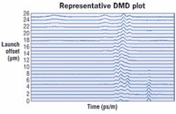
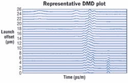
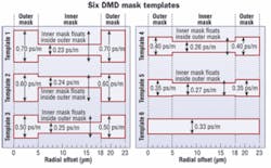
As the OM3 standards developed, however, the application of this process feedback tool as a means to assess fiber bandwidth performance took root. During development of the standards, a method was sought to assess the performance of fibers based on DMD results. The first screen that was developed was the use of DMD mask templates, or the DMD mask, which consists of six unique templates. Each template allows a defined quantity of differential mode delay in picoseconds/meter (ps/m) as a function of radial location in the fiber. Each template has an inner and outer mask as well as four sliding masks that must be met to satisfy OM3 designation criteria.
Before DMD data are evaluated against the masks of each template, however, the raw data are processed to condition the results. These conditioning steps accommodate significant shortcomings in the measurement systems at the expense of the screening capability of the fiber selection method.
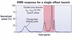
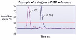
The most dramatic example of DMD screening limitations is the use of full width quarter maximum (FWQM) amplitude to define the differential mode delay between leading and lagging pulses. The use of FWQM allows the DMD mask to disregard all leading and trailing optical signals that have an amplitude of less than 25 percent.
An example of this filtering is presented in the figure, DMD response for a single offset launch. The plot shows a normalized output of a DMD trace at a single core radial position. The received power is normalized to the peak power of the pulse response, and the leading and lagging FWQM points are identified to calculate the DMD at that location. In this instance, a leading pulse has a normalized amplitude that is slightly less than 25 percent of maximum, so the entire pulse is disregarded in the determination of DMD and not applied against the mask templates. The omission of this leading pulse, however, could affect actual system performance and link functionality in a high-speed system.
Manufacturing cost vs. accuracy
It's apparent that this conditioning step may overlook or minimize the impact of significant response attributes that could affect system performance. In addition to the omission of leading or lagging pulses and other received signals that are less than 25 percent of the normalized maximum, the use of FWQM filtering may also allow measurement systems to have excessive optical and electrical ringing.
Therefore, results from less robust measurements systems can be used to determine compliance relative to the DMD mask, since spurious signals that are less than 25 percent of the normalized maximum power are disregarded. While these systems may reduce manufacturing cost, they present a cost in measurement precision and accuracy that could translate to functional performance issues.
Other special measurement adaptations, such as the arithmetic removal of the reference signal, are incorporated in the use of the DMD mask. The removal provides expediency at the cost of accuracy. To properly remove the measurement system response to isolate the fiber response, the reference pulse needs to be deconvolved from the received pulse response in a manner consistent with linear time-invariant (LTI) systems theory.
Simple arithmetic subtraction of the reference pulse may lead to a lack of scalability in mask results. For example, two measurement systems, each having different time domain responses, may produce different results for the same fiber. The mask may indicate compliance due to the simplistic arithmetic subtraction of the reference while more appropriate measures that involve deconvolution could show that the fiber may not be capable of high speed system performance.
The DMD mask also has issues relative to its ability to ensure that all fibers will be compatible with all standard-compliant transmitters. Each template allows a varying quantity of mode delay as a function of radial position in the core. Varying time delays in the inner and outer regions represent the more stringent or relaxed requirements that must be met based on the spot size characteristics of the transceivers used in high-speed systems.
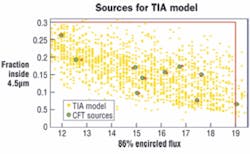
The DMD results only need to pass one of the six mask templates to qualify as an OM3 fiber, but this could result in functional issues in the application. Actual systems utilize 850-nm vertical cavity surface emitting lasers (VCSELs) that have defined encircled flux (EF) limits. The limits define how much light must be launched at a specific radial location in the fiber core. For OM3 fibers, VCSELs could emit up to 30 percent of its power within the first 4.5 µm of core radius and at least 86 percent of its light out to the first 19 µm of core radius.
Obviously, certain combinations of VCSELs with fibers that pass a particular mask could lead to performance issues. For example, the coupling of a hot outside VCSEL source with a fiber that has a larger allowance for modal dispersion at the higher radial positions could compromise the satisfactory performance of the system link. Furthermore, the mask only applies to the first 23 µm of radius for a nominal 25-µm radius core fiber. While VCSELs may have a slightly smaller launch spot than traditional sources (e.g., LEDs), the mode delay in the higher radial positions should not be ignored.
Typically, a multimode fiber is provided with a measured value that describes the bandwidth performance of the multimode fiber. DMD mask yields an output that is unfamiliar to bandwidth users. If a mask value is provided, the fiber is assigned a set of delay values in picoseconds per meter (ps/m). In some cases, only a pass/fail statement against the OM3 specification may be provided with no additional measurement information. The delay values may be convertible to a more familiar bandwidth value, but their significance and scalability are not the same as the tried and true normalized bandwidth values of MHz•km that are common in the optical and copper communications industries.
The inherent shortcomings in the DMD mask forced innovations in the bandwidth measurement community. Endusers needed a familiar bandwidth value in MHz•km that would clearly indicate performance capability and assure performance in a high-speed optical system with compliant VCSELs. The DMD measurement continued to be the most powerful means available to characterize the fiber, but it had to be significantly improved through innovation to achieve the desired objective of an actual bandwidth value.
The DMD measurement and its output needed to be sufficiently capable to cover a broad dynamic range and frequency response range to allow its use in a more powerful bandwidth metric. If the DMD output was sufficiently refined and robust, it could be coupled with the profile of the light spot from actual transceivers, and a reliable calculated bandwidth value could be obtained. Conveniently, VCSEL vendors had defined restrictions on EF, so the optical power distribution that was launched into the fiber was well understood. The combination of these two attributes—fiber DMD and the VCSEL launch power location—seemed to be a path toward a superior metric.
Enter EMBc
Fiber vendors arrived at calculated effective modal bandwidth (EMBc) as a solution to this problem. EMBc is a metric that allows the calculation of a unique bandwidth value for any combination of fiber and source optical power distribution, whether measured from an actual transmitter or theoretically derived to bound a defined optical source EF distribution. The EMBc measurement method was the second screening metric that was incorporated in OM3 standards.
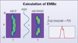
The calculation of EMBc places higher standards on the performance of the DMD measurement system. Hours of engineering design and careful component selection are necessary to create an EMBc-capable DMD measurement system. Unlike the DMD mask, which disregards output pulse power below 25 percent amplitude, EMBc uses the entire received optical signal to calculate a bandwidth value. Therefore, noise sources, source/detector ringing, and other spurious measurement system artifacts must be greatly reduced or eliminated.
An EMBc-capable DMD system must use the highest performance laser sources (typically a Ti:Sapphire laser), detectors, and peripheral optical and mechanical components. An exceptionally narrow spot size for the probe signal must be used to ensure that the group delays at each specific location across the fiber core are properly measured. Additionally, fundamentally sound practices, such as accurate centering of the probe fiber relative to the fiber under test, proper selection of the oscilloscope's time window, appropriate time domain sampling techniques, and the full collection of all received power, are imperative to yield a precise and accurate EMBc.
The EMBc value is applied in a manner that is different from the DMD mask. While a fiber is required to pass just one mask to be classified as OM3-capable, a fiber is required to have EMBc values (bandwidth in MHz•km) above a standards-defined threshold value when evaluated with the launch power distribution of 10 representative VCSELs. The 10 launch power distributions fully span the EF specification for OM3 capable VCSELs that was described earlier. Any moderate delay flaws in the DMD profile of the fiber or any excessive mode delays at any localized area would result in a significant reduction of EMBc. This is contrary to the application of the DMD mask, which disregards signal that is less than 25 percent of the normalized maximum.
The minimum of all 10 EMBc values is used to establish the pass/fail measurement of record (called the minimum calculated effective modal bandwidth, or minEMBc). This ensures that the worst case pairing of fiber DMD and VCSEL source conservatively defines the performance of the fiber. Therefore, minEMBc is a much more rigorous test of compliance and functionality than the DMD mask.
The power of 10
Closer inspection of the figure Sources for TIA model shows that there is a wide range of possible compliant transmitter EF values that range from hot centered (those with optical power approaching 30 percent at 4.5 µm) to hot outside (barely 86 percent optical power at 19 µm). The 10 weights are fully representative of the theoretical transmitter distribution that was considered in the determination of OM3 specifications.
Independent evaluations of transmitter EF distributions have confirmed the suitability of the use of these 10 standard weights relative to the full distribution of actual sources. In fact, these studies have discovered another point about the transmitter EF distributions. Recent papers have suggested that the most limiting sources (Sources 1 and 5 as seen in the figure Calculation of EMBc) are rare in the actual transceiver population. A review of actual minEMBc results on production fibers reveals that these two weights produce the vast majority of the minEMBc values. In other words, the sources that drive the minEMBc values are highly unlikely to be found in an actual system. This fact provides an additional layer of conservatism to minEMBc, since the most common sources tend to yield an EMBc that is much higher than the minEMBc value. Furthermore, minEMBc is robust and can be easily adapted to new standards and transceiver distributions as new sources and applications enter the market.
Improved performance standards for DMD measurement systems may explain how EMBc evolved, but it does not speak to the most important requirement for a fiber attribute—linkage to system functionality. As noted previously, a multimode optical fiber must only meet one of six mask templates to satisfy OM3 requirements. The maximum DMD in any one fiber can vary from 0.33 to 0.7 ps/m, depending on the mask template that the fiber satisfies. If a fiber passes a given mask template, for example, it could be paired with a VCSEL that is not optimized for a fiber with that specific DMD profile. As a result, the association between mask performance and actual system functionality can be problematic.
EMBc, however, utilizes the two most significant pieces of link data—the fiber's DMD profile and the characteristics of the VCSEL light source. The minimum EMBc of 10 diverse lasers is used to certify OM3 performance. The use of the most conservative EMBc values provides the greatest assurance that the fiber will operate as designed when paired with a standard- compliant VCSEL in an optical link.
The assessment of minEMBc as a function of system BER or dispersion penalty may lead some to conclude that the metric does not have full correlation with all VCSEL sources. Since the minEMBc value is the bandwidth measurement of record, a conforming fiber will be fully compatible with the full range of standard-compliant transceivers. Each unique standard-compliant VCSEL will have its own unique EF, which will yield a unique EMBc. The specific EMBc is typically well above the specified requirements for OM3 fibers. As a result, fibers with a passing minEMBc will provide satisfactory performance in OM3 systems when paired with a compliant transceiver.
The comparison of BER or dispersion penalty for a given link, however, may not correlate well with the minEMBc value for the fiber. To optimize correlation with BER and dispersion penalty, the comparison of EMBc and system functionality must utilize the weight for the VCSEL that is being studied.
Recent technical papers are reflecting the trend toward assessment of system functionality based on calculated EMBc for a given source/fiber combination rather than the use of the very conservative minEMBc value. Future work is planned to show the correlation of specific fiber/source EMBc with system performance attributes, such as power penalty or bit error ratio.
Alternative methods
If imitation is the sincerest form of flattery, EMBc should be blushing. Industry standards organizations recently agreed to develop calculated overfilled bandwidth (OFLc) as an alternate measurement method for direct OFL bandwidth measurements. OFLc will use the DMD of a fiber and an agreed upon weight to calculate an OFL bandwidth value. This method will eliminate the tremendous variability in measured OFL bandwidth values due to the allowable variation in overfilled launches and other measurement system differences among benches.
While it may not make OFL a more functional measurement, it should promote measurement agreement when equally capable DMD systems are being compared.
JEFFREY ENGLEBERT is supervisor, Center for Fiber-Optic Testing, and STEVEN GARNER is multimode measurements engineer at Corning Optical Fiber (www.corning.com/opticalfiber).
