Best practices for fiber-optic installation
Any errors made during installation can result in significant costs.
By Paul Hospodar, L-Com Global Connectivity
Fiber installations are undoubtedly the most prominent media for the transmission of the massive amounts of data over short, medium, and long distances. When it comes to fiber installations, some often-overlooked practices are fairly critical in maintaining a fiber run’s signal integrity. This article aims to illuminate some common failure points of fiber runs and how to prevent them fromoccurring.
A tightening power budget
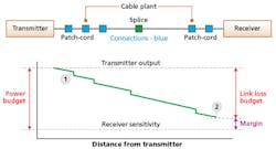
As fiber-optic technology advances, so does the inflexibility of the link budget. Many factors will degrade a signal from Point A to Point B, some of which can be planned for, such as inherent cable loss as well as loss due to splices, bends, connector heads, and even ultimately aging of the lasers in the transmitter. Other factors are unpredictable, such as cable mishandling. A survey conducted by Fluke Networks illuminates some of these unplanned failure points fairly well. Their list, which goes from most common failure modes to least, includes dirty endfaces, poor polishing, broken connectors, mislabeling, shattered endfaces, bad splices, and finally, excessivebending.
Link-loss margins have also only grown tighter. In the new 568.3-D standard, the Telecommunications Industry Association (TIA) lessened the fiber cable attenuation minimum from 3.5 dB/km to 3.0 dB/km in order to increase the maximum supportable distances between transmitter and receiver. Some fiber deployments often need multiple points, all contributing their own respectivelosses.
The Fiber Optic Association developed this illustration of a sample power budget, in its explanation of power and loss budgets (www.thefoa.org/tech/lossbudg.htm).
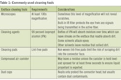
Connector cleanliness
Dirty fiber endfaces account for 85 percent of attenuation loss issues, according to the textbook Cabling: The Complete Guide to Copper and Fiber-Optic Networking by Bill Woodward. Contamination comes in many forms, including dust particles attracted to the connector surface by moisture ingress (e.g. moisture-laden isopropyl alcohol), dust particles attracted to the connector surface by static electricity, dust particles rubbed into the connector surface causing permanent scratching, and fingerprintoil.
During testing, dirty endfaces are often the culprit for inconsistent results after multiple measurements. Dirty reference cables can also cause faulty readings with test equipment such as gain or unusually high loss. Not only is the possibility of dirt readily entering the connector very high to begin with, but so is the risk of pushing around dirt creating scratches and grooves, causing permanent damage. The tiny fiber core is easily obstructed with dirt particles, finger oils, and various types of mishandling. This can obstruct the light source (or sensor) or force the two endfaces apart, generating scattering, dispersion, and ultimately, intermittent connections and network downtime. Consequently, it is important to clean both connectors before testing a cable regardless of whether or not dust caps were placed on them during storage. Microscopes and cleaning kits are therefore available for all types of fiberconnectors.
It is common practice for technicians to use microscopes with at least 100x magnification to visually inspect connector endfaces. While this might be adequate to visualize dust particles, it might not suffice for an inspection of an endface after polishing or be enough to see smaller grooves that can degrade performance. Defects with diameters on the order of tens of microns may be better seen up to 250x; this is especially true with the tiny dimensions of singlemode fibers. In applications where higher powers are used (e.g. CATV, specific telephone networks), it is important to use a microscope with a filter to block any laser light. More often than not, the source of light comes from an LED as opposed to a laser. Still, laser light is invisible to the eye and direct viewing of it does not cause pain. Because of this, a technician subjected to extended exposure to laser light will likely not close the iris of the eye, causing irreversible damage to theretina.
Simple fiber-optic connector cleaning systems employ a relatively straightforward kit that includes a solvent to remove oily contamination and a lint-free rubbing surface. Some processes leverage a bottle of 90-percent isopropyl alcohol (IPA) and dry wipes, while others involved premoistened alcohol pads, which offer both the solvent and cleaning surface in one package. As referenced earlier, one consideration that comes with utilizing a bottle of IPA is that over time it will begin to collect moisture and a technician that uses this moisture-penetrated alcohol will find that the surface of the fiber will take longer to dry, leaving it susceptible to dirt. Alcohol pads can effectively mitigate the risk of this occurring. Variations of this cleaning system include dry connector cleaners with extendable treated, lint-free tips for recessed connectors removing dirt, oil, and debris from various adapters (e.g. SC, LC, MU, MPO).
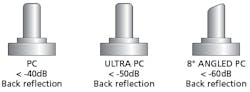
The most common polish finishes are physical contact (PC), ultra-physical contact (UPC), and angled physical contact (APC).
Compressed air cans can be a useful tool for cleaning dust off endfaces. The gas inside the cans is compressed into a liquid form. Typically the liquid stays at the bottom of the can when it is held upright. At certain angles, however, some of the liquid can be released. More often than not, the cold liquid rapidly evaporates off of the connector endface. Still, it may be more practical to hold the canister upright and level to the endface to prevent liquid from spraying out. And, in case some liquid may have come out, spraying for a prolonged period of time (more than 3 seconds) should remove/disperse anyliquid.
Improperly installed connectors
Both the dimensions and materials in fiber cable construction can make it difficult to learn how to install a connector properly. There are a few variations of connector termination kits available. Some require epoxies and polishing while others come prepolished but require a precise cleave. Typically, the main point of failure in fiber terminations is an improperly polished connector. This is likely due to the fact connector polishing is a task that takes a bit of finesse and therefore has an associated learning curve. The act of polishing has two main goals: 1) shaping the end tip until the desired shape is accomplished; 2) smoothening the shape to minimize lightrefraction.
Common polish topologies include flat, physical contact (PC), ultra-physical contact (UPC), and angled physical contact (APC). A technician can either hand polish a connector, or, use a polishing machine for more consistent results. Either way, errors still occur so there are methods that attempt to sidestepthem.
Preventing improperly installed connectors—Prepolished splice terminations, or no-epoxy/no-polish (NENP) connectors, tend to eliminate the common failure point of a poor polish and allow a very fast termination. A number of tools are available to terminate with a prepolished connector. Of all these steps, a cleanly cleaved fiber is likely the most complextask.
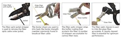
Tools commonly used to install a fiber connector include the jacket stripper, shears, fiber (buffer) stripper, and cleaver.
The buffer coating that protects the fiber is often clear and difficult to see. In the step that requires the fiber-optic stripper, it is important to ensure all the coatings are entirely removed and the fiber is cleaned with IPA. Any coating left will not fit into the connector splice and will therefore degrade performance. Drawing a visual mark on the coated buffer is also recommended to better place the cable on the cleaver. The buffer coating will have to line up with the guides stop or a pad on the cleaver depending on which variant of the tool is used. After the cleave is accomplished the fiber is inserted into the connector to be crimped or clamped into place with a rotatingcam.
As a consideration, an experienced technician probably would use nearly the same amount of time to install multiple epoxy-and-polish (EP) connectors and multiple NENP connectors. Additionally, a NENP connector is generally more expensive than an EP connector. With that being said, it is still far less error-prone and, the kit materials do not require replenishment—the same cannot be said for the epoxy and polishing films needed for an EPkit.
Testing and inspecting the fiber—After terminating a cable, there are two main assessments that can be made to judge the integrity of the connector head: a visual inspection and a method to measure reflectance. The reflectance (or back reflection) of the connector measures the amount of light that is reflected back to the source due to the imperfections in the polished interface. A poor polish will send many reflections back, causing a higher loss in the connector and ultimately, the entire installation. A good visual inspection of the connector will likely yield a good reflectance. However, less-experienced technicians may not be able to adequately visually discern an acceptable fiber connector so an additional test may be a helpful redundancy. Power meters, visual fault locators and continuity testers are therefore helpful not only for large installations, but on a case-by-case basis to reduce scrap rates in training newinstallers.
Personal safety
Safety precautions should be taken when handling fiber cabling. This is the case for any shard of glass, from fiberglass to a broken bottle. Mishandling thin pieces of glass can have insidious side effects. Stomach irritation or even internal hemorrhaging can occur after ingesting fiber particles. Glass shards can occur when cleaving or accidentally breaking a fiber during termination. These can turn into glass splinters, which are very difficult tosee.
When terminating a cable, an installer would benefit from wearing goggles and protective clothing such as an apron. This prevents glass shards from getting into the eyes. Additionally, it is recommended to wash the hands before rubbing eyes or touching any food as a precaution. Black rollup mats that hold polishing plates in place can also help identify fiber splinters. These splinters should be disposed of in a scrap trash can with tweezers. The goal is to mitigate the risk of getting glass shards into sensitive areas, and because these shards can be hard to detect, it might be better to operate as though they will inevitablyoccur.
The practice of terminating a fiber-optic cable is a well-understood technique with a number of practical options. Nevertheless, any errors that run through from the manufacturing stage to the installation stage can cost major sums for data centers and companies that rely on their fiber installation for connectivity. This type of downtime is typically avoided at all costs, so any effort to mitigate this in the initial stages can serve to be a great advantage.u
Paul Hospodar is fiber-optic product manager for L-Com Global Connectivity.

