Foxwoods expansion bets on outside-plant design
Construction of a new casino required the replacement of outside-plant infrastructure.
David J. McCaul, Consolidated Services Group
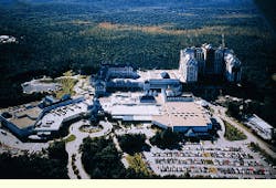
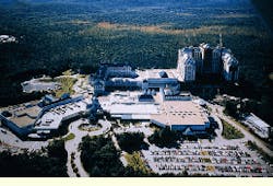
Located in Ledyard, CT, the Foxwoods Hotel Resort and Casino maintains a sprawling campus on more than 300 acres. A popular gaming location in the Northeast, the complex includes five main buildings, three of which contain casinos, including a bingo and special-events hall with 1500 slot machines. Two of these buildings also house restaurants and general offices, and one has a 300-room hotel. Also on site are a waste-treatment plant and a 200-room hotel with several restaurants.
With that number of buildings and thousands of visitors each day, the resort and casino rely heavily on the communications system, which, in turn, is shaped by the campus outside-plant design. In that design, the main communications cables feeding the remote buildings are routed from the main building, which contains the demarcation room. A common point for all the interconnects on site, which are routed through conduit, is the first manhole located outside the main building.
This outside-plant design had to be reworked recently when Foxwoods began construction of a smoke-free casino. A major part of this project involved moving the main manhole serving the complex`s cabling and replacing the cable running through it.
Foxwoods called on Consolidated Services Group (csg-- Norwood, MA) to design and build the revamped outside-plant system. csg was given six weeks to complete the project, and the company had to do the work without disrupting service to the gaming facility. The installer brought in a project designer from its Denver, CO, office, and a team was assembled on site in a just a few days.
Planning to address customer concerns
Before the design process could begin, csg conducted an analysis of Foxwoods`s current cabling needs, as well as any possible future requirements. One of the many concerns that surfaced in this analysis was the lack of outside-plant cabling documentation for the current system, which had been installed over several years by a number of different vendors. The waste-treatment facility also lacked documentation of its existing conduit and cabling.
Another concern was possible downtime that might be required to install the new cabling links, especially since it could impact the 3000 telephones at the complex. Consisting of private-branch exchange lines, phone service was delivered to pay phones, modem lines, security modem lines, and emergency phones. Overall, 35,000 feet of copper cabling would be affected.
The data network was also on the list of concerns. The fiber- optic interconnects linking the site contained 350 strands of multimode fiber-optic cable, running in 75,000 feet of cabling, and the majority of the strands were in use. The project called for the replacement of the singlemode fiber-optic interconnect, as well as the coaxial-cable interconnect. A 24-strand fiber-optic cable also had to be installed to and terminated at the remote hotel facility.
In addition, Foxwoods asked csg to coordinate the project with its local-exchange carrier and the local cable-television vendor.
Surveying the site
Once the customer`s concerns were noted, csg began the next phase of the design--conducting a site evaluation. One of the most important steps in the design, this evaluation included a site survey, an evaluation of the existing facilities, and an inventory of current capabilities, including those of the local-exchange carrier and cable-TV vendor.
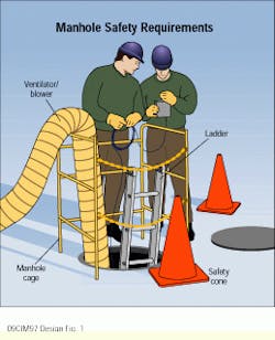
For csg, safety was an important consideration during this design process. The company requires that its personnel attend and pass a confined-spaces safety course before entering manholes. When conducting a site survey of underground facilities, the following equipment is required: a complete manhole package, with safety harness, tripod with winch, ventilator/blower, gas detector, safety cones, manhole hook, vehicle safety beacon, manhole cage, and manhole ladders. A "Utility workers ahead" sign must also be posted.
Before the site survey can begin, facility drawings that show roads, buildings, and conduit locations for the existing cables, as well as plans for the new ones to be installed, must be obtained. Butterfly drawings for each manhole should also be generated by the designer.
For the Foxwoods project, the survey started in the demarcation room. The designer asked the following questions: What is feeding in from the conduits? What systems are the cables feeding? Are any of these cables unused or dead?
All the live cables and spare cables had to be noted, and cables traced to their termination points. At this point a full-documentation study was done, including all termination points with type of termination, plus crossconnect-wire sheets documenting crossconnects.
Existing conditions must also be reviewed. When installing additional cables, the following questions must be answered: Is there a pathway for these cables? Are additional cable trays needed? Is there room for new protectors and fiber-optic enclosures? A drawing of the demarcation room should show existing equipment, termination blocks, the room dimensions, and available space. csg surveyed the Foxwoods demarcation room and then did an identical survey of the entrance facilities at the remote buildings.
Once the inside work was done, a survey of the outside, underground facilities was begun. Paying attention to safety, csg protected the manhole work area by erecting safety cones and a manhole cage. Once ventilation was established, the manhole was successfully tested for breathability, and csg started the ventilator and dropped the ladder into the hole.
Some of the questions the installer needed to answer at this point were: Is the manhole racked? Are there any splices in the manhole? Are the existing cables attached to the manhole racks? If there are no racks, are the cables attached to the side of the manhole or left hanging or on the floor?
Documenting the cabling plant
csg was faced with many challenges in documenting the waste-treatment facility. The main question was: How can you design an underground facility when a record of the existing facility does not exist? There are several methods for determining conduit or duct-bank routing--contact the system installer for as-builts, which are drawings that record what has been installed. If the facility is on public land, you can contact your local utility or the local city or town for the record. A visual check can also be performed if the installation is relatively new. You can also look for the road cuts--the patched surface resulting from the duct-bank installation. However, the latter method may not be an accurate determination of the duct-bank path. You can also use an underground cable locator.
Because the project was built on a federal reservation, the local utility companies and the town had no drawings on file. The csg project engineer decided to contact the duct-bank installer, and he also used an underground cable locator. Within an hour, he had located approximately 800 feet of undocumented conduit and two manholes. With this new data, csg generated revised drawings of this area of the Foxwoods facility as part of the design package.
Creating a system design
With the survey and analysis completed, csg determined that the existing cable would have to be removed from the existing manhole and then fed back into the building through a new manhole. The alternative was to splice it in several places. Given this choice, Foxwoods staff decided to replace the existing cable with new throughout the facility. This resulted in multiple 900-pair, gel-filled fiber-optic cables, 350 strands of multimode fiber in eight cables, and two 48-strand singlemode fiber-optic cables being pulled. Also in the mix were a 24-strand singlemode fiber-optic cable owned by the local exchange carrier, and one coaxial cable owned by the cable-TV vendor. The issue at hand became how to reinstall all of this cable in only two conduits.
The site survey revealed that the two existing conduits were filled with dead and unused cables. With those two conduits emptied and two other conduits available, it was determined that there would be adequate space to splice all four into the new manhole. To best utilize the conduits, the proper cables had to be assigned to the most appropriate conduit. The specification called for the local exchange carrier to have its own conduit. The second conduit was used to carry a 900-pair, gel-filled cable, which was to be used as the main feed into the facility; it was to be spliced to the new cable in the relocated manhole using a gel-filled enclosure. The third conduit held two 144-strand multimode fiber-optic cables, and two 48-strand singlemode fiber- optic cables. The design called for installing one 12-strand singlemode fiber-optic cable for cable TV to replace the coaxial cable, and one 24-strand multimode fiber-optic cable was used to feed the three remote switch cabinets. The conduit also carried four additional 24-strand multimode fiber-optic cables.
The design called for the fiber-optic cable to be installed in innerduct inside the conduits. In the manholes, a split version of the innerduct was used. The manholes also required racking on all four walls.
Implementing the design
While the actual cabling installation went smoothly, problems arose while placing equipment for the additional fiber-optic and copper-cable terminations. The main demarcation room lacked the wall space for a termination field, and the existing cable tray was filled to capacity. csg recommended that the existing cable tray be expanded from 18 inches to 24 inches, and a free-standing rack be added for mounting protection equipment.
Although the customer asked that the existing wall-termination field be reworked to provide additional terminations, that could not be done. Instead, csg proposed an additional wall be used for a new wall field.
Cutting over the remote-switch and slick cabinets was accomplished by moving the existing fiber-optic jumpers from the older fiber cables to the new ones. Slick cabinets are used by phone companies to run fiber-optic cable to a cabinet; in that cabinet the optical signal is converted to electrical for transmission over copper lines. The pay phones, modems, and security circuits were taken down a pair at a time to ensure that each end of the cable would be disabled at the same time. The fiber-optic data connections were repatched one jumper at a time to reduce the downtime per system and server. The cable-TV transfer from coaxial to fiber-optic cable simply involved exchanging the existing amplifier in the building for one with a fiber-optic input. The facility cut-over was conducted between 1 AM and 3 AM. With a window as narrow as that, it was essential to have accurate documentation of the system.
The key to any installation is preplanning, and with a fast-track project such as this one, it was important to choose a material manufacturer that could meet the project`s requirements. For this project, csg chose Essex Group Inc. Communications Products (Fort Wayne, IN), which was able to ship the cables on spools cut to length for each cable run. When spools hold cable cut to length, it reduces cable waste and project labor. Because csg`s storage space was limited, the company chose to have the materials shipped directly to the site. csg also maintained a just- in-time delivery arrangement with Pacer Electronics (Woburn, MA) that required Pacer to have a truck on the job site at 6 AM on days that materials were expected to be needed.
David J. McCaul is the executive director of Consolidated Services Group, a telecommunications firm that provides services in data, voice, and video communications systems. The company is located in Norwood, MA. McCaul is also a member of csg`s national project team.
The campus of Foxwoods Hotel Resort and Casino spans 300 acres and includes five main buildings. The gaming facility recently constructed a cigarette smoke-free casino.
Working in an underground environment such as a manhole requires a number of pieces of equipment for adequate safety. They include safety harness, tripod with winch, ventilator/blower, gas detector, safety cones, manhole hook, vehicle safety beacon, manhole cage, and manhole ladders. A "Utility workers ahead" sign is also necessary.
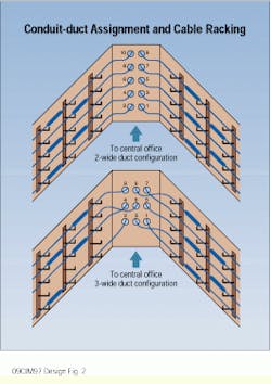
To survey the manhole, document the existing cables, including entrance conduit and exiting conduit. Shown here are the racking arrangement and the order of duct selection for single-racked manholes.
Meeting a casino/resort`s cabling needs
David Barnett, Essex Group Inc. Communications Products
Communications cabling comes in an impressive range of configurations. This variety arises from the interaction of National Electrical Code requirements, bandwidth needs, and the economic considerations of the customer.
Designing and installing the cabling plant for a project of the proportions of that at Foxwoods Hotel Resort and Casino (Ledyard, CT) required extensive cabling-plant design knowledge. It was critical that the proper cable be selected for each of the varying applications and locations in the complex.
Often cable manufacturers can offer guidance about the correct cable design to select for different uses. For example, the contractors for the Foxwoods project relied on Essex Group Inc. Communications Products (Fort Wayne, IN) to assist them in specifying the cables to be used as indoor backbones for the telephone system. Large-pair-count armm cables best fitted the casino`s requirements. armm is a Bell Coding System designation for shielded riser-type cable.
"This product is a natural for use inside a building for a high-density network whose bandwidth needs don`t exceed Category 3," says Jeanie Baer, registered communications distribution designer (rcdd), manager of product engineering for Essex. "It combines the construction and transmission characteristics of a standard outside-plant cable with the materials needed for communications-cable riser rating when used in riser shafts."
According to Baer, the features of armm cable also make it easy to transition to outdoor cable, because of the similarities in design and transmission characteristics between the two cable types.
Baer adds that Essex`s goal as a cable manufacturer is to match the customer`s requirements with the performance characteristics of the product. "We feel that this is a critical cooperative element in the design of an effective network," she notes. "Tell us your cable requirements and we`ll advise you of the cable that best meets them and still meets or exceeds industry standards."
She continues, "If an off-the-shelf cable won`t work, we may design one that will."
David Barnett is the manager of marketing for Essex Group Inc. Communications Products (Fort Wayne, IN).


