Enhancing passive optical networks with structured cabling
From the February, 2015 Issue of Cabling Installation & Maintenance Magazine
Customers can obtain the benefits of PON and maintain the benefits of structured cabling in a non-proprietary approach.
By Kevin J. Stronkowsky, Siemon
Passive optical networks (PONs) have emerged as an alternative to structured cabling-based switched networks with application-independent telecommunications outlets in the work area. Capable of distributing voice, video and data to the desktop over one singlemode fiber, PONs offer the benefit of transmission distances that are well in excess of 100 meters (328 feet), as well as easy deployment and reduced pathway and conduit-space requirements due to the smaller size of a singlemode cable.
PONs make good sense in some environments, especially where maintaining the required 100-meter distance of a switched network architecture supported by balanced twisted-pair copper cabling is not feasible. However, these systems most commonly use direct equipment connections or "point-to-point" cabling that is not standards-compliant and does not support the benefits of structured cabling specified for commercial buildings in ANSI/TIA-568-C.1 and ISO/IEC 11801 Edition 2.2 When PONs are deployed using standards-compliant structured cabling systems, flexibility to support future moves, adds, and changes (MACs) is significantly improved and administration is enhanced.
PON refresher
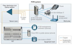
Based upon GPON (ITU G.984.2) or EPON (IEEE 802.3ah) protocols used in outside-plant technology that support fiber-to-the-building (FTTB) or fiber-to-the-home (FTTH) network architectures, a PON is an in-building optical fiber network that enables the distribution of voice, video and data over one singlemode fiber. The main components of a PON are:
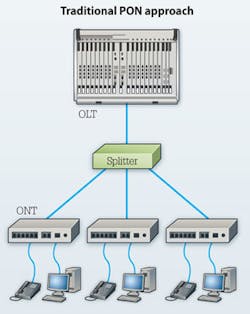
A) Optical line terminal (OLT) located in the equipment room or data center;
B) Passive optical splitters located in the telecommunications closet on each floor;
C) Optical networking terminals (ONTs) located in end-user work areas.
In a typical PON, one singlemode fiber runs from the OLT to the splitter and from there to each ONT, which converts the optical signal into multiple balanced signals for transmission over copper twisted-pair cabling and vice versa. At the work area, copper cabling extends from the ONT to work area equipment (e.g. computers, phones, printers). Typically one ONT is used per work area and supports up to four services. While a PON is often referred to as a passive technology due to the passive optical splitters that are integral to the system, it is important to note that the ONT is an active device that requires local power at the work area to maintain services.
The singlemode optical fiber that connects to each ONT originates from the OLT. The fiber from the OLT is split into multiple fibers at the optical fiber distribution hubs containing passive optical splitters. From there, the fibers connect to ONTs. A PON configuration is shown in the first figure.
Why structured cabling?
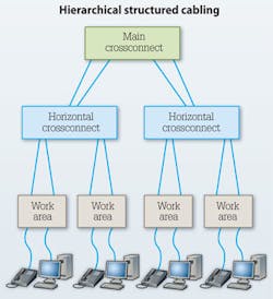
When the first data networks were built, end-user terminals were connected via "point-to-point" connections with coaxial or traditional bus cabling. As computing needs increased and new equipment and connections were needed, point-to-point cabling added complexity and cost. In response, industry standards organizations developed and now recommend a hierarchical structured cabling infrastructure for connecting multiple network devices and supporting multiple applications, as shown in the above figure. This industry standards-based structured cabling approach enables interoperability between equipment and cabling vendors.
Now considered the cornerstone of in-building LANs, an organized, consistent and interoperable structured cabling platform is one that can be cost-effectively managed to ensure reliable, long-term performance. TIA and ISO/IEC standards recommend structured cabling because it offers the following benefits.
- Ease of upgrades to new technologies
- The ability to replace equipment with minimal service disruption
- Support for easier MACs
- The ability to change equipment vendors
- Enhanced administration and labeling capability
- Support of backup and redundant connections
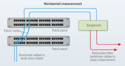
Compliance with both ANSI/TIA-568-C.1 and ISO/IEC 11801 Edition 2.2 requires a minimum of two permanent links for each work area. Using a structured cabling approach, the permanent horizontal links from the work areas connect to corresponding copper patch panels at horizontal crossconnects located in the telecommunications room, as shown in the figure on the opposite page. Using patch cords, these patch panels connect to other patch panels that correspond to the ports of the active equipment (e.g. router, switch). This creates a highly flexible "any-to-all" configuration in which any equipment port can be connected to any work-area outlet. MACs are easy and require simple patch-cord changes between patch panels. The permanent cable connections between the patch panels and their corresponding work area outlets remain fixed.
As long as standards-based high-performance structured optical fiber and copper cabling capable of supporting two or three generations of active electronics is used, the permanent horizontal and backbone cables deployed in a structured cabling application infrastructure only need to be installed once. Upgrading the network to support new applications and higher transmission speeds only requires upgrading the active equipment.
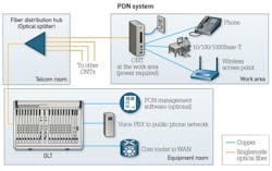
In contrast, a traditional PON deployment directly interconnects the OLT, splitters, and ONT via one-strand singlemode optical fiber connections, as shown to the right. This has implications that include the following.
- Lack of compliance with TIA and ISO standards, which require two permanent links per work area
- Inability to easily accommodate MACs
- Difficult upgrades of ONTs at the work area to support emerging applications such as Power over Ethernet Plus and 10GBase-T
- Inability to upgrade to Ethernet networking, which requires two fibers for duplex transmission
- Being locked into a single vendor for PON equipment (i.e. ONTs and OLTs)
- No backup capabilities and lack of redundant connections between splitters and OLTs
- Difficulty administering and labeling connection points
A structured approach
While traditional "point-to-point" PON deployments do not conform to TIA and ISO/IEC structured cabling requirements, the good news is that customers have the option to specify a standards-based approach to PON deployment that will greatly enhance the flexibility of PON systems with the existing advantages of structured cabling.
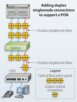
As shown on the previous page, the first step to supporting PON with a structured cabling approach involves replacing the direct one-fiber singlemode connection between the OLT and the splitter with a main crossconnect that supports a duplex singlemode fiber backbone connection to each outlet. A single fiber equipment-cord can still be used for making the connection from the crossconnect to the PON equipment.
The direct singlemode connection between the splitter and the ONT is also replaced by a duplex singlemode connection using interconnect patch panels in the telecommunications room and a duplex fiber telecommunications outlet into which the ONT is plugged. Again, a single fiber equipment-cord can be used for making the connection between the ONT and the outlet, and between the splitter and the interconnect panel.

Adding a duplex singlemode fiber connection between the OLT and the splitter, and between the splitter and the ONT, provides additional support for migration to future Ethernet networking technologies, which require a duplex fiber connection for transmission. Installed once, these permanent duplex singlemode connections will provide unlimited support and interoperability for future standards-based technology and bandwidth. The additional fiber can also be used to provide redundancy for the system, significantly improving overall reliability.
Implementing a main crossconnect between the OLT and splitter, as well as between the interconnect panels between the splitter and ONT, also facilitates MACs. OLT fiber ports can be easily located to any splitter, and splitter ports can be easily allocated to any ONT--all with a simple patch-cord change. Connecting the ONT to a work-area outlet also allows for ONTs to be easily moved to a different work area, and it allows for faster ONT upgrades.
A shown above, the next step to ensuring a standards-compliant PON system deployment is to provide a second permanent link at the work area using a structured cabling scenario. Most commonly, this is a Category 6A or higher-rated balanced twisted-pair connection. The final figure depicts an ideal PON-ready backbone and horizontal cabling topology for buildings having a main crossconnect and a horizontal crossconnect only. This recommended minimum topology can also be applied to larger build-outs that support Cabling Subsystem 2 and 3 runs and an intermediate crossconnect, or configurations in which the PON splitter is housed in a zone enclosure. Subsystem 2 can be either four-pair balanced twisted-pair or multimode optical fiber cabling depending on length and other needs.
The use of Category 6A for the second outlet connection ensures compliance with the latest TIA and ISO/IEC standards that require a minimum of two outlets per work area. Category 6A also happens to be the horizontal cabling media recommended by TIA-1179 for new healthcare facilities, and by TIA-4966 for new educational facilities, as well as being recommended for use in new installations in the TIA-568-D series of cabling standards that are in development.
The addition of a Category 6A outlet also supports adoption of remote powering technologies and high-speed data transmission. To date, PON ONTs only optionally support Power over Ethernet (PoE) Type 1 (i.e. maximum output of 15.4W from the power source) power injection. There are also currently no PON solutions on the market with the capability to support speeds of 10 Gigabits per second. In contrast, Category 6A is 10GBase-T-ready and supports all remote powering applications, including Type 1 up to four-pair enabled 100W remote powering applications such as Power over HDBase-T, and pending IEEE 802.3bt Type 4 PoE. Category 6A port availability can defer or prevent the need to replace PON equipment at various work areas that may require these services in the future.
For deployments that exceed the maximum 100-meter distance limitation for Category 6A, a duplex Om3 or Om4 multimode fiber connection is recommended for the second work-area connection to support Ethernet transmission speeds of 10 Gbits/sec. However, an optical-fiber-cabling-only design to the work area will limit remote power delivery to just those applications supported by the ONT.
By supporting PON systems with structured cabling that includes duplex optical fiber links between PON equipment and a second Category 6A outlet at the work area, customers can obtain all the touted advantages of PON while maintaining all the benefits of structured cabling. They can also support the latest applications enabled by Category 6A and ensure compliance with industry standards. This approach supports PON equipment in a non-proprietary manner just as structured cabling supports any pluggable Ethernet switch or device regardless of manufacturer.
Kevin J. Stronkowsky is global product manager for fiber-optic systems at Siemon (www.siemon.com).
Archived CIM Issues

