Build a fiber-optic test box
Jim Greer
Allied Computer Group
Problem
A fiber-optic network has been installed and tested. However, when you tie in the hubs to create a ring, the network fails. With the white-light source provided in the test kit, you are not able to see all the problems or inconsistencies associated with terminating fiber-optic cables.
Solution
Build your own light source using colored light-emitting diodes because these will show more definition. By using this fiber-optic test box, you will clearly see terminations. If colored LEDs are used, any small abnormality that was hidden before will stand out prominently.
Procedure
1) Purchase the following materials at a hobby or electronics store:
--Small plastic project box
--Six colored LEDs (red or green)
--Six 1.5-kilo-ohm resistors
--Small on/off switch
--9-volt battery
2) Mount the LEDs on top of the box for easy accessibility.
Note: We used six LEDs because this is the number of ST connectors installed in fiber modules mounted in the fiber termination boxes.
3) Locate the switch in an unobtrusive location. If you do not use an on/off switch, then you have to unplug the battery each time you use the kit.
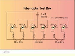
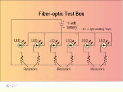
4) Mount the resistors inside the box.
5) Secure the 9-volt battery with a cable tie to keep it in place and allow replacement when necessary.
6) Wire the switch to one side of the battery.
To use the test box:
Patch the six fiber cores to the box by using quality patch cords.
View the cores on the other end of the fiber by using the microscope from your test kit. Improper terminations will appear fuzzy or will show cracks or chips. These cracks are not necessarily at the connector, however. Problems farther down the core will still appear at the connector tip.
Note: This test box does not replace other methods of testing fiber-optic cables; it provides further understanding of why a problem exists.
The 9-volt battery is wired to one side of the six resistors, which in turn, are attached to one side of the six light-emitting diodes. The other side of the LEDs is connected to the opposite side of the battery. The LEDs should be rated for 6 to 12 volts and the resistors rated 1.5 kilo-ohms.
Jim Greer is lead technician at Allied Computer Group, Milwaukee, WI.

